background image


Installation 


Fillcontrol Auto Compact — 20.10.2020 - Rev. D 


English  — 7 


Contact water meter (optional accessory) 

Reflex Fillsoft softening system (optional accessory) 

Fillcontrol Auto Compact 

WC  Make-up line to the device 
DC  Make-up line to the system circuit 
LIS  Filling level monitoring 

• 

External signal cable to the Levelcontrol make-up variant 

LS  Insufficient water switch 
PIS  Pressure sensor 

• 

For the Magcontrol make-up variant 


Prepare the connection as follows: 
1. 

Select the "DN" nominal diameter for the make-up lines. 
• 

At a length of up to 10 metres: DN 15. 

• 

At a length beyond 10 metres: DN 20. 

Flexibly connect the make-up lines. 
2. 

Flexibly connect the "DC" make-up line to the pump's shut-off valve. 

3. 

Connect the "DC" make-up line to the system circuit. 

4. 

Flexibly connect the "WC" make-up line to the shut-off valve of the mains 
separator tank. 

5. 

Connect the "WC" make-up line to the external fresh water main. 


The make-up lines are connected. 


 

Note! 
Use a pressure reducer in the "WC" make-up line if the mains water 
pressure exceeds 6 bar. 


 

Note! 
For selecting the make-up variants, see chapter 6.4 "Switching and 
make-up variants"
 on page 7 . 


6.4


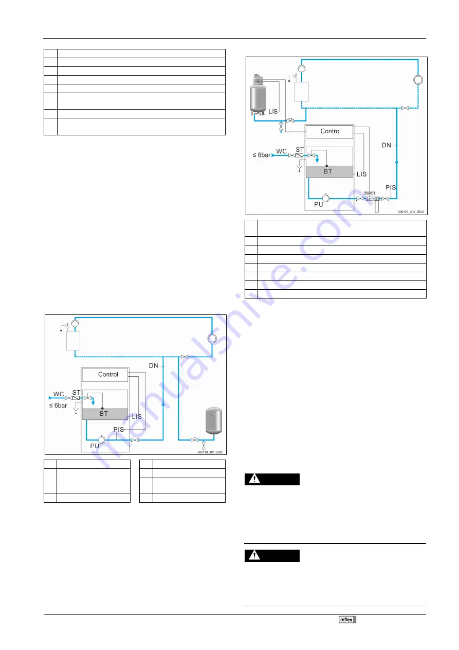
Switching and make-up variants 

"Magcontrol" pressure-dependent water make-up into the system circuit 


WC  Make-up line to the device 


PU  Pump 

ST  Dirt trap at the shut-off valve 

of the mains separator tank 


PIS  Pressure sensor 


DN  Nominal diameter of the 

make-up line 

BT  Mains separator tank 


LS  Insufficient water switch 


Water make-up to system circuits with a diaphragm expansion vessel. 
The device must be installed in the vicinity of the diaphragm expansion vessel to 
ensure that the filling pressure for the fresh water make-up is recorded by the 
"PIS" pressure transducer in the device. For calculating the filling pressure, see 
chapter 7.2 "Determining the P

0

 minimum operating pressure for the controller" 

on page 9 . 


"Levelcontrol" level-dependent water make-up into the system circuit. 


LIS  Level sensor 

–  

To monitor the filling level in the pressurisation unit 

WC  Make-up line to the device 
ST  Dirt trap at the shut-off valve of the mains separator tank 
BT  Mains separator tank 
PU  Pump 
PIS  Pressure sensor 
LS  Insufficient water switch 
DN  Nominal diameter of the make-up line 


Water make-up to system circuits with a pressurisation unit. 
Pressurisation units are equipped with filling level monitors. When the filling 
level falls below the minimum level, the pressurisation unit sends a signal to the 
device controller. The controller activates the pump. The system circuit is 
replenished with fresh make-up water.


 

Note! 
For setting the make-up variants, see chapter 9.2.1 "Customer menu" on 
page 12 . 


 

Note! 
You may combine the device with softening systems (e.g. Reflex 
Fillsoft); available as optional accessories, see chapter 4.6 "Optional 
equipment and accessories" on
 page 5 . 


When using a Reflex Fillsoft, the PIS pressure transducer is installed downstream 
of the fitting and other installed components, such as a water meter. This 
prevents malfunctions when measuring the pressure. 
Remove the PIS pressure transducer from the device and fit it in the 
corresponding position in the system circuit. To do so, use a T-piece as a 
connector in the piping system. 
 

6.5


Electrical connection 

 DANGER 


Risk of serious injury or death due to electric shock. 
If live parts are touched, there is risk of life-threatening injuries. 
• 

Ensure that the system is voltage-free before installing the device. 

• 

Ensure that the system is secured and cannot be reactivated by other 
persons. 

• 

Ensure that installation work for the electric connection of the device is 
carried out by an electrician, and in compliance with electrical 
engineering regulations. 


 DANGER 


Risk of serious injury or death due to electric shock 
Some parts of the device's circuit board may still carry 230 V voltage even 
with the device physically isolated from the power supply. 
• 

Before you remove the covers, completely isolate the device controller 
from the power supply. 

• 

Verify that the main circuit board is voltage-free. 


Summary of Contents for Fillcontrol Auto Compact

Page 1: ...Fillcontrol Auto Compact 20 10 2020 Rev D GB Operating manual Original operating manual ...

Page 2: ...on 6 6 4 Switching and make up variants 7 6 5 Electrical connection 7 6 5 1 Terminal diagram 8 6 5 2 RS 485 interface 8 6 6 Installation and commissioning certificate 8 7 Commissioning 8 7 1 Requirements for initial commissioning 9 7 2 Determining the P0 minimum operating pressure for the controller 9 7 3 Filling the device with water 9 7 4 Parametrising the controller in the Customer menu 9 7 5 F...

Page 3: ...safety information can result in death or severe irreversible injuries CAUTION Damage to health The sign in combination with the signal word Caution indicates danger failure to observe the safety information can result in minor reversible injuries ATTENTION Damage to property The sign in combination with the signal word Attention indicates a situation where damage to the product itself or objects ...

Page 4: ...3 Maximum working pressure in bar 1 2 3 4 4 Function 1 FQIRA contact water meter optional accessory 2 Fillsoft optional accessory 3 Fillcontrol Auto Compact PIS Pressure sensor WC Fresh water make up line to the device LS Signal line for insufficient water switch DC Make up line to the system circuit LIS External signal line from a pressurisation unit The device controller uses the pump to regulat...

Page 5: ...pressure in bar 6 Installation DANGER Risk of serious injury or death due to electric shock If live parts are touched there is risk of life threatening injuries Ensure that the system is voltage free before installing the device Ensure that the system is secured and cannot be reactivated by other persons Ensure that installation work for the electric connection of the device is carried out by an e...

Page 6: ...ation 1 Position the device 2 Create the water side connections of the device to the system Use connections with the same dimensions at the device for all lines 3 If required create the interfaces according to the terminal plan 6 3 1 Fitting the add on components WC Connection of the make up line to the mains separator tank OC Connection of the mains separator tank overflow DC Connection of the ma...

Page 7: ...into the system circuit LIS Level sensor To monitor the filling level in the pressurisation unit WC Make up line to the device ST Dirt trap at the shut off valve of the mains separator tank BT Mains separator tank PU Pump PIS Pressure sensor LS Insufficient water switch DN Nominal diameter of the make up line Water make up to system circuits with a pressurisation unit Pressurisation units are equi...

Page 8: ...ontroller for example Set the controller to Levelcontrol User optional 17 Make up 230 V 18 Make up 230 V 22 PE shield Pressure analogue input For output to the display For make up actuation For the Magcontrol make up variant Factory 23 Pressure signal 24 Pressure 18 V 29 A RS 485 interface User optional 30 B 31 GND 32 24 V supply E1 Supply for E1 and E2 Pre wired bridged 33 E1 Contact water meter ...

Page 9: ...or at the impeller using a screwdriver Switch the pump to a zero volts state before turning the pump at the fan wheel with a screwdriver ATTENTION Device damage due to pump start up Pump damage may occur when the pump starts up if you turn the pump motor at the impeller using a screwdriver Switch the pump to a zero volts state before turning the pump at the fan wheel with a screwdriver Fill water ...

Page 10: ...e up functions 8 1 2 Manual mode Use For testing and maintenance tasks Start Press Manual on the controller The auto LED on the controller operating panel and PU in the display flash as visual indicators of manual operation Functions After starting the manual mode you can manually activate and deactivate the pump Proceed as follows Press OK on the controller s operating panel to activate the pump ...

Page 11: ...en the make up variants Levelcontrol and Magcontrol Magcontrol In system circuits with a diaphragm expansion vessel Levelcontrol in system circuits with a pressurisation unit Min op pressure 01 8 bar The system displays the Minimum working pressure message when you have set the Magcontrol make up variant Enter the value for the minimum operating pressure Note Calculation of minimum operating press...

Page 12: ...ormation about the software version 9 2 1 Customer menu The device controller is shipped with the following default settings Use the Customer menu to adjust these values to local conditions In special cases it is possible to further adjust the values in the Service menu Parameter Setting Comment Language DE Display language Parameter Setting Comment Fillcontrol XX Magcontrol For systems with diaph...

Page 13: ...th Magcontrol Set value for the maximum pressure has been exceeded Safety valve defective Pipe to system has insufficient diameter Check the actuating pressure of the safety valve Replace the safety valve Install new pipe to the system with sufficient diameter Quit 11 Make up volume Only if With water meter is activated in the Customer menu Set value of the water meter has been exceeded Leakage in...

Page 14: ...2 1 Customer menu on page 12 Minimum operating pressure P0 Safety valve pressure PSV x Annually 10 2 Exterior leak test Check the following device components for leaks PU pumps and screw fittings Seal any leaks at the connections or replace the connections if required Seal leaking screw connections or replace if required 10 3 Cleaning the dirt trap Clean the ST dirt trap according to the following...

Page 15: ... dismantling block off all water side connections to the device 2 Disconnect the system from the power supply and secure it against unintended reactivation 3 Disconnect the power cable of the device from the power supply 4 Disconnect and remove all cables from the terminals of the device controller 5 Undo all hose and pipe connections between the device and the system and remove them completely 6 ...

Page 16: ... D EN Installation and commissioning certificate This device has been installed and commissioned in accordance with the instructions provided in the operating manual The settings in the controller match the local conditions Typ Type P0 PSV Fabr Nr Serial No ...

Page 17: ...SI1416enD 11 20 Reflex Winkelmann GmbH Gersteinstraße 19 59227 Ahlen Germany 49 0 2382 7069 0 49 0 2382 7069 9546 www reflex winkelmann com ...

Reviews: