Installation
Reflexomat XS — 02.16.2022 - Rev. A
English — 19
2.
Document any damage.
3.
Contact the forwarding agent to register your complaint.
6.2
Preparatory work
Condition of the delivered device:
•
Check all screw connections of the device for tight seating. Tighten the
screws as necessary.
Preparing the device installation:
•
No access by unauthorised personnel.
•
Frost-free, well-ventilated room.
–
Room temperature range: +5 °C to +40 °C.
–
Protect the device against direct effects of the weather.
•
Level, stable flooring.
–
Ensure sufficient bearing strength of the flooring before filling the
vessel.
•
Filling and dewatering option.
–
Provide a DN 15 filling connection according to DIN EN 1717.
–
Provide an optional cold water inlet.
–
Prepare a drain for the drain water.
•
Electrical connection,
•
Use only approved transport and lifting equipment.
–
The load fastening points on the vessel must be used only as
installation resources.
Note!
No transverse and longitudinal acceleration forces were allowed for
when dimensioning the product. If installing in a seismic area
(earthquake zone > 0.1 m/s² according to EN 1998-1), on-site safety
measures must be implemented.
6.3
Execution
ATTENTION
Damage due to improper installation
Additional device stresses may arise due to the connection of pipes or system
equipment.
•
Pipelines must be connected so there are no residual forces and
torques and must be routed so they are free from vibrations.
•
If necessary, provide support structures for the pipelines or equipment.
•
If you have any questions, please contact Reflex After Sales & Service.
Proceed as follows for the installation:
•
Position the device.
•
Create the water-side connections of the control unit to the system.
•
Create the interfaces according to the terminal plan.
6.3.1
Locating the vessel
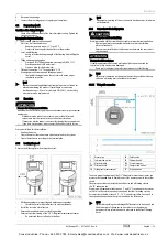
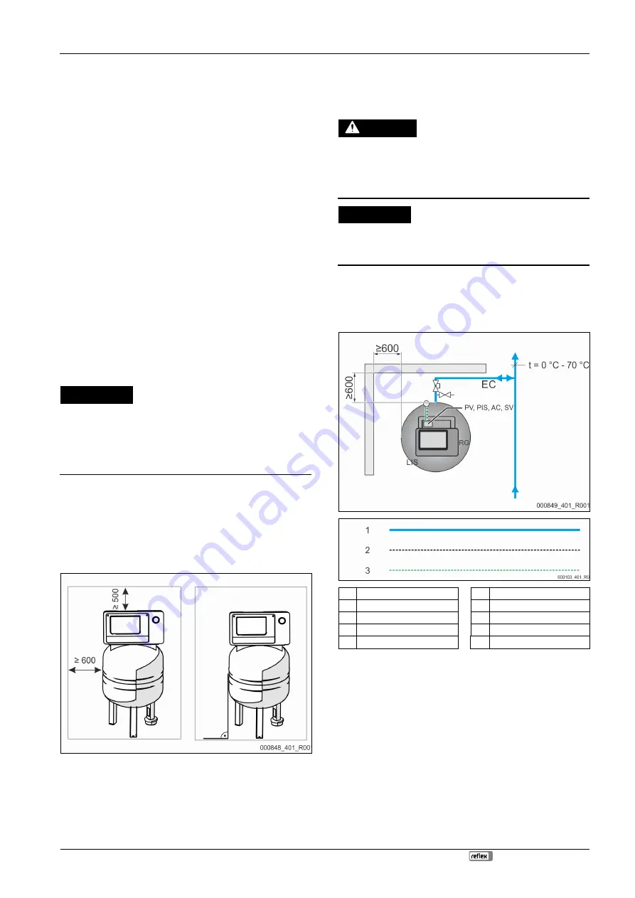
Observe the following tips when siting the vessel:
•
All flange openings are inspection and maintenance openings.
–
Locate the vessel with a sufficient side and top clearance.
•
Install the vessel on a level surface.
•
Ensure a perpendicular and free-standing position.
•
Ensure proper functioning of the "LIS" Filling level measurement sensor.
–
Do not attach the vessel firmly to the floor.
Note!
The weight measuring cell is not resistant to water hammer; also it must
not be painted.
6.3.2
Connection to the facility system
CAUTION
Risk of injury due to falls or stumbling
Bruising caused by falls or stumbling over cables or pipes during installation.
•
Wear personal protective equipment (helmet, protective clothing,
gloves, safety boots).
•
Ensure proper installation of cables and pipes between the control unit
and the vessels.
ATTENTION
Damage to cables and pipes
If cables and pipes are not routed professionally between tanks and the
control unit, they may become damaged.
•
Route cables and pipes in a professional manner over the flooring.
Note!
Each vessel connection on the water side must be provided with a cap
valve and a draining device (included in the scope).
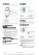
6.3.2.1
Water-side connection
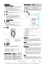
1
Water pipe
SV Safety valve
2
Compressed air line
PV Solenoid valve
3
Electrical cable
PIS Pressure sensor
RG Primary vessel
AC Compressed air line
LIS Filling level measurement
EC
Expansion line
To ensure proper functioning of the "LIS" filling level measurement sensor, you
must use the supplied hose to flexibly connect the primary vessel to the system
circuit.
The primary vessel has a protected shut-off device and a draining valve in
the "EC" expansion line.
Use points with temperatures between 0 °C and 70 °C to connect to the system
circuit. This is the return in heating systems and the flow in cooling systems.
At temperatures below or above 0 °C – 70 °C, you must install in-line vessels in
the expansion line between the system circuit and the Reflexomat.
Note!
For details regarding the switching of Reflexomats or in-line vessels and
the dimensions of the expansion lines, please see the planning
documents. More information is also provided in the Reflex Planning
Guide.
Cooke Industries - Phone: +64 9 579 2185 Email: sales@cookeindustries.co.nz Web: www.cookeindustries.co.nz


