106
Chapter 4
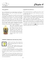
Wall Control Panel Blue Backlighting Description:
• The holding tank icon in the lower right hand corner
of the control panel is not lighted. Toilet system is off
or not receiving power.
• The holding tank icon is normally green. This means
the holding tank is less than full.
• The holding tank icon is red. The holding tank is full
or near full with the flush lockout (prevents Flush
operation when holding tank is full) activated.
•
Tank icon flashes
• Sleep mode (non-use for 8 hours) causes the lights to
go out. Pushing the fill or flush button momentarily
will return lighting cycle.
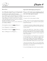
Single Flush Override of Flush Lockout
1. If the holding tank is full the flush lockout cycle will
not allow the bowl to be flushed and the flush button will
be lighted red.
2. For emergency use only the flush button can be held for
8 seconds and a flush will occur. This can be accomplished
because the full sensor connected to the holding tank
is usually placed a bit below the actual full capacity of
the tank. Flushing more than 5 times using the override
feature may force waste into plumbing system.
Regal is
not responsible for damage to equipment, or injury or
death due to overflow of waste due when flush lockout
is overridden.
Again, refer to toilet vendor information
in the owner’s information packet.
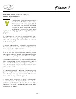
CAUTION
!
POSSIBLE OVERFLOWING
OF THE WASTE HOLDING TANK
CAN OCCUR DUE TO USING
THE SINGLE FLUSH OVER-RIDE FUNCTION.
FOR EMERGENCY USE ONLY.
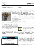
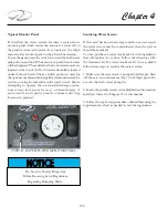
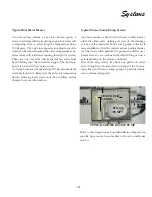
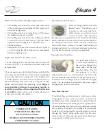
Typical Dockside Pump-Out
There is a fitting located on the deck
labeled “waste.” This fitting is used
to pump out the waste tank. Nor-
mally a pump out station is found
at most marinas. After removing
the fitting cover a special hose is inserted into the fitting
and the machine then removes the waste. Normally there
is a charge for the service. Make sure they connect the
hose to the “waste” fitting. Of course when cruising in
international waters the overboard discharge pump may
be used. See the section on using the macerator.
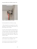
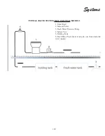
As stated earlier there is
a waste filter installed in
the
vent
line between the
waste tank and the port
thru-hull fitting. The fil
-
ter’s purpose is to keep
objectionable odors to a minimum from the waste tank.
It is recommended that the filter be changed yearly. It can
be ordered from your Regal dealer or from marine supply
stores. The waste filter is mounted in the sump (engine
compartment) near the waste tank.
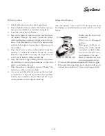
Typical In-Line Vent Filter
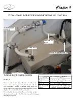
Gray Water System
If installed, the gray water system is used in areas where
dumping fresh water waste products overboard is
prohibited. Gray water originates from on board sinks and
showers. With this system all the gray water is pumped into
the waste holding tank via the shower sump pump system
verses directly overboard. The holding tank periodically
needs be to be pumped out by a marina pump out station
through the “waste” fitting on the deck. Use the waste
water portion of the monitoring panel at the ship’s main
control panel to check waste water levels.
Summary of Contents for 26 EXPRESS
Page 1: ...OWNER S MANUAL 26 EXPRESS 26 XO 4 2019...
Page 28: ...28 Chapter 2 NAVIGATION LIGHT RULES...
Page 50: ...50 Chapter 3...
Page 51: ...51 Rules Of The Road...
Page 73: ...73 Systems TYPICAL 12 VOLT HELM SWITCH PANELS PORT SWITCH PANEL STARBOARD SWITCH PANEL...
Page 121: ...121 Systems...
Page 122: ...122 Chapter 4...
Page 123: ...123 Systems...
Page 124: ...124 Chapter 4...
Page 125: ...125 Systems...
Page 126: ...126 Chapter 4...
Page 127: ...127 Systems...
Page 128: ...128 Chapter 4...
Page 129: ...129 Systems...
Page 130: ...130 Chapter 4...
Page 153: ...153 Engine Controls REGAL 26 XO TANK LABEL...
Page 177: ...177 Engine Controls SEA STAR STEERING SYSTEM SCHEMATIC OVERVIEW...
Page 262: ...262 Chapter 8 OVERBOARD DISCHARGE PAN DRAIN TYPICAL VECTOR COMPACT AC SYSTEM AIR FILTER...
Page 275: ...275 Cosmetic Care Maintenance...
Page 294: ...294 Chapter 9 HOT WATER HEATER...
Page 298: ...298 Chapter 9 STEREO DIAGNOSTIC CHART...
Page 299: ...299 Troubleshooting STEREO DIAGNOSTIC CHART...
Page 300: ...300 Chapter 9 STEREO DIAGNOSTIC CHART...
Page 303: ...303 Troubleshooting THRUSTER BOW...
Page 304: ...304 Chapter 9 TYPICAL WINDLASS...
Page 321: ...321 Technical Information TECHNICAL DRAWINGS...
Page 325: ...Technical Information 322 26 EXPRESS GALVANIC ISOLATOR WIRING...
Page 326: ...Technical Information 323 TYPICAL NMEA 2000 NETWORK COMPONENTS...
Page 328: ...Technical Information 325 26 EXPRESS TYPICAL DC GROUND CIRCUITRY...
Page 329: ...Technical Information 326 26 EXPRESS TYPICAL TRIM TAB SWITCH CIRCUITRY...
Page 330: ...Technical Information 327 26 EXPRESS TYPICAL GFCI CIRCUITRY...
Page 331: ...Technical Information 328 26 EXPRESS TYPICAL FIRE EXTINGUISHER GROUND CIRCUITRY...
Page 332: ...Technical Information 329 26 EXPRESS TYPICAL STEREO BLUETOOTH WIRING EARLIER...
Page 333: ...Technical Information 330 26 EXPRESS TYPICAL SWITCH PANEL HARNESS PLUG CIRCUITRY...
Page 334: ...Technical Information 331 26 EXPRESS TYPICAL SWITCH PANEL CIRCUITRY...
Page 335: ...Technical Information 332 26 EXPRESS BATTERY MANAGEMENT PANEL FRONT CIRCUITRY...
Page 336: ...Technical Information 333 26 EXPRESS BATTERY MANAGEMENT PANEL REAR CIRCUITRY...
Page 337: ...Technical Information 334 26 EXPRESS DOMESTIC 120 VOLT MAIN AC PANEL...
Page 338: ...Technical Information 335 26 EXPRESS OVERSEAS 230 VOLT MAIN AC PANEL...
Page 339: ...Technical Information 336 26 EXPRESS DOMESTIC 120 VOLT MAIN AC PANEL...
Page 340: ...Technical Information 337 26 EXPRESS GALLEY ELECTRIC BREAKOUT 1...
Page 341: ...Technical Information 338 26 EXPRESS GALLEY ELECTRIC BREAKOUT 2...
Page 342: ...Technical Information 339 26 EXPRESS GALLEY ELECTRIC BREAKOUT 3...
Page 343: ...Technical Information 340 26 EXPRESS GALLEY ELECTRIC BREAKOUT 4...
Page 344: ...Technical Information 341 26 EXPRESS GALLEY ELECTRIC BREAKOUT 5...
Page 345: ...Technical Information 342 26 EXPRESS GALLEY ELECTRIC BREAKOUT 6...
Page 347: ...Technical Information 344 26 EXPRESS MACHINERY LAYOUT PROFILE VIEW EXPLODED...
Page 348: ...Technical Information 345 26 EXPRESS MACHINERY LAYOUT TOP VIEW EXPLODED...
Page 353: ...Technical Information 350 26 EXPRESS TYPICAL BOW PLAN WINDLASS...
Page 359: ...Technical Information 356...
Page 360: ...Technical Information 357...
Page 361: ...Technical Information 358...
Page 362: ...Technical Information 359...
Page 363: ...Technical Information 360...
Page 364: ...Technical Information 361...
Page 365: ...Technical Information 362...
Page 366: ...Technical Information 363...
Page 367: ...Technical Information 364...
Page 368: ...Technical Information 365...
Page 369: ...Technical Information 366...
Page 370: ...Technical Information 367...
Page 371: ...Technical Information 368...
Page 373: ...Technical Information 370...
Page 374: ...Technical Information 371...
Page 375: ...Technical Information 372...
Page 376: ...Technical Information 373...
Page 377: ...Technical Information 374...
Page 379: ...Technical Information 376...
Page 381: ...Technical Information 378...
Page 382: ...Technical Information 379...
Page 383: ...Technical Information 380...
Page 384: ...Technical Information 381...
Page 386: ...Technical Information 383...
Page 387: ...Technical Information 384...
Page 388: ...Technical Information 385...
Page 389: ...Technical Information 386...

