187
Vessel Operation
STARTING GUIDELINES
Position the remote control handles in the neutral position.
Keep passengers seated and away from controls.
Note: With earlier models the Volvo EVC-D control
station will be activated once the ignition key is in the
“ON” position (key position l) At this point the neutral
“
N
” icon will display a green light .
Next, turn the key to the start position (key position lll).
You will hear the starter cranking over the engine. When the
engine starts release the key switch. If additional cranking
attempts are needed, the key must be returned to the
0
position first.
If the engine does not start, refrain from cranking the
engine over 10-12 seconds. Allow the starter and battery
a chance to recover. Advance the remote control in the
neutral throttle position only as recommended in the
engine manual. Do not race the remote control in the
neutral position.
On later EVC-D systems, turn the key to the “ON”
position and then to the start position. Release the key. The
starter will continue to crank until the engine starts.
With this system once the keys are engaged in the automatic
start position they are disengaged if you try to turn them
again to the start position.
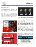
On the newest Volvo engines a key fob system is used
to start the engines. The system uses two main parts; the
key panel and the key fob. Two key fobs come with dual
engine installation along with a 2.5” key panel. The key
panel uses lighted icons to show active ignition and start/
stop positions. Theft protection is vastly improved with
the E-key system.
If the starter stays engaged for more than 30 seconds
the circuit is automatically cut to protect the starter from
overheating. If this happens, let the starter cool for several
minutes before attempting to restart the engine.
Note: With all the above systems, refer to the Volvo
operator’s manual for further information.
STARTING & STOPPING
The following general information covers
starting and stopping your engines. Read
and understand all previous information
on remote controls, fueling and
operational procedures. Pay particular
attention to all labels. Refer to the engine
operation manual for in-depth propulsion
system information.
Review all pre-departure information. Before starting
your engines make sure all canvas is removed and stored.
Start engines only in a well ventilated location to avoid
diesel exhaust buildup. Make sure all battery switches are
activated. Close and lock the center windshield section.
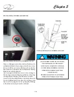
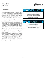
AVOID PERSONAL INJURY OR DEATH!
WHEN ENGINE IS RUNNING
TRANSOM DOOR MUST
BE CLOSED AND LOCKED.
SWIM PLATFORM
AND LADDER MUST NOT BE IN USE.
WARNING
!
WARNING
!
AVOID SERIOUS INJURY OR DEATH!
THE OPERATOR OF THE CRAFT
MUST HAVE COMPLETE CONTROL
OF THE HELM STEERING STATION
WHILE THE VESSEL IS MOVING.
NEVER LEAVE THE HELM
STEERING STATION UNATTENDED
WHILE THE VESSEL IS MOVING.
Summary of Contents for 26 EXPRESS
Page 1: ...OWNER S MANUAL 26 EXPRESS 26 XO 4 2019...
Page 28: ...28 Chapter 2 NAVIGATION LIGHT RULES...
Page 50: ...50 Chapter 3...
Page 51: ...51 Rules Of The Road...
Page 73: ...73 Systems TYPICAL 12 VOLT HELM SWITCH PANELS PORT SWITCH PANEL STARBOARD SWITCH PANEL...
Page 121: ...121 Systems...
Page 122: ...122 Chapter 4...
Page 123: ...123 Systems...
Page 124: ...124 Chapter 4...
Page 125: ...125 Systems...
Page 126: ...126 Chapter 4...
Page 127: ...127 Systems...
Page 128: ...128 Chapter 4...
Page 129: ...129 Systems...
Page 130: ...130 Chapter 4...
Page 153: ...153 Engine Controls REGAL 26 XO TANK LABEL...
Page 177: ...177 Engine Controls SEA STAR STEERING SYSTEM SCHEMATIC OVERVIEW...
Page 262: ...262 Chapter 8 OVERBOARD DISCHARGE PAN DRAIN TYPICAL VECTOR COMPACT AC SYSTEM AIR FILTER...
Page 275: ...275 Cosmetic Care Maintenance...
Page 294: ...294 Chapter 9 HOT WATER HEATER...
Page 298: ...298 Chapter 9 STEREO DIAGNOSTIC CHART...
Page 299: ...299 Troubleshooting STEREO DIAGNOSTIC CHART...
Page 300: ...300 Chapter 9 STEREO DIAGNOSTIC CHART...
Page 303: ...303 Troubleshooting THRUSTER BOW...
Page 304: ...304 Chapter 9 TYPICAL WINDLASS...
Page 321: ...321 Technical Information TECHNICAL DRAWINGS...
Page 325: ...Technical Information 322 26 EXPRESS GALVANIC ISOLATOR WIRING...
Page 326: ...Technical Information 323 TYPICAL NMEA 2000 NETWORK COMPONENTS...
Page 328: ...Technical Information 325 26 EXPRESS TYPICAL DC GROUND CIRCUITRY...
Page 329: ...Technical Information 326 26 EXPRESS TYPICAL TRIM TAB SWITCH CIRCUITRY...
Page 330: ...Technical Information 327 26 EXPRESS TYPICAL GFCI CIRCUITRY...
Page 331: ...Technical Information 328 26 EXPRESS TYPICAL FIRE EXTINGUISHER GROUND CIRCUITRY...
Page 332: ...Technical Information 329 26 EXPRESS TYPICAL STEREO BLUETOOTH WIRING EARLIER...
Page 333: ...Technical Information 330 26 EXPRESS TYPICAL SWITCH PANEL HARNESS PLUG CIRCUITRY...
Page 334: ...Technical Information 331 26 EXPRESS TYPICAL SWITCH PANEL CIRCUITRY...
Page 335: ...Technical Information 332 26 EXPRESS BATTERY MANAGEMENT PANEL FRONT CIRCUITRY...
Page 336: ...Technical Information 333 26 EXPRESS BATTERY MANAGEMENT PANEL REAR CIRCUITRY...
Page 337: ...Technical Information 334 26 EXPRESS DOMESTIC 120 VOLT MAIN AC PANEL...
Page 338: ...Technical Information 335 26 EXPRESS OVERSEAS 230 VOLT MAIN AC PANEL...
Page 339: ...Technical Information 336 26 EXPRESS DOMESTIC 120 VOLT MAIN AC PANEL...
Page 340: ...Technical Information 337 26 EXPRESS GALLEY ELECTRIC BREAKOUT 1...
Page 341: ...Technical Information 338 26 EXPRESS GALLEY ELECTRIC BREAKOUT 2...
Page 342: ...Technical Information 339 26 EXPRESS GALLEY ELECTRIC BREAKOUT 3...
Page 343: ...Technical Information 340 26 EXPRESS GALLEY ELECTRIC BREAKOUT 4...
Page 344: ...Technical Information 341 26 EXPRESS GALLEY ELECTRIC BREAKOUT 5...
Page 345: ...Technical Information 342 26 EXPRESS GALLEY ELECTRIC BREAKOUT 6...
Page 347: ...Technical Information 344 26 EXPRESS MACHINERY LAYOUT PROFILE VIEW EXPLODED...
Page 348: ...Technical Information 345 26 EXPRESS MACHINERY LAYOUT TOP VIEW EXPLODED...
Page 353: ...Technical Information 350 26 EXPRESS TYPICAL BOW PLAN WINDLASS...
Page 359: ...Technical Information 356...
Page 360: ...Technical Information 357...
Page 361: ...Technical Information 358...
Page 362: ...Technical Information 359...
Page 363: ...Technical Information 360...
Page 364: ...Technical Information 361...
Page 365: ...Technical Information 362...
Page 366: ...Technical Information 363...
Page 367: ...Technical Information 364...
Page 368: ...Technical Information 365...
Page 369: ...Technical Information 366...
Page 370: ...Technical Information 367...
Page 371: ...Technical Information 368...
Page 373: ...Technical Information 370...
Page 374: ...Technical Information 371...
Page 375: ...Technical Information 372...
Page 376: ...Technical Information 373...
Page 377: ...Technical Information 374...
Page 379: ...Technical Information 376...
Page 381: ...Technical Information 378...
Page 382: ...Technical Information 379...
Page 383: ...Technical Information 380...
Page 384: ...Technical Information 381...
Page 386: ...Technical Information 383...
Page 387: ...Technical Information 384...
Page 388: ...Technical Information 385...
Page 389: ...Technical Information 386...


