228
Chapter 7
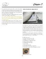
HIGH WATER ALARM-BILGE
The high-water alarm warns the skipper of a possible
emergency in the bilge area. There is an automatic float
switch installed in the center bilge. If the water rises over
a predetermined level the bilge switch sends a signal to the
helm mounted alarm. This sump float switch normally is
elevated from the position of the automatic bilge pump
switches.
If the alarm sounds bring the vessel back to an idled posi-
tion in neutral and turn off the engines. Open the engine
hatch and find the cause of the problem.
Possible causes are:
1. Engine or generator hose leak.
2. Mufflers or exhaust hose leak.
3. Hull leak due to striking an object.
4. Water or waste tank leak.
5. Plumbing feed hose leak.
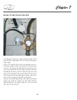
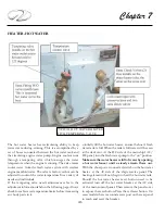
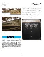
High Water
Automatic Switch
Helm High Water Alarm
6. Seacock leak.
7. Heat exchanger leak.
8. Transducer or underwater light leak.
9. Water heater tank or heat exchanger hose leak.
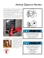
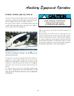
Note that the hot water heater utilizes a safety device called
a T & P valve (See the illustration on previous page). Just as
a home unit the valve provides relief should the hot water
heater overheats. In an emergency the valve will open and
hot water will exit into the bilge.
This situation will cause the bilge pump system to operate
until the water supply is disconnected.
As a safety precaution always disconnect the hose
from the marina water supply to the water dockside
inlet valve on the boat when leaving the vessel for
extended periods.
On select newer models there may be a piping connected
to a thru-hull from the T & P valve on the hot water heater.
In this case a blown relief valve will exit water overboard
verses the bilge.
Summary of Contents for 26 EXPRESS
Page 1: ...OWNER S MANUAL 26 EXPRESS 26 XO 4 2019...
Page 28: ...28 Chapter 2 NAVIGATION LIGHT RULES...
Page 50: ...50 Chapter 3...
Page 51: ...51 Rules Of The Road...
Page 73: ...73 Systems TYPICAL 12 VOLT HELM SWITCH PANELS PORT SWITCH PANEL STARBOARD SWITCH PANEL...
Page 121: ...121 Systems...
Page 122: ...122 Chapter 4...
Page 123: ...123 Systems...
Page 124: ...124 Chapter 4...
Page 125: ...125 Systems...
Page 126: ...126 Chapter 4...
Page 127: ...127 Systems...
Page 128: ...128 Chapter 4...
Page 129: ...129 Systems...
Page 130: ...130 Chapter 4...
Page 153: ...153 Engine Controls REGAL 26 XO TANK LABEL...
Page 177: ...177 Engine Controls SEA STAR STEERING SYSTEM SCHEMATIC OVERVIEW...
Page 262: ...262 Chapter 8 OVERBOARD DISCHARGE PAN DRAIN TYPICAL VECTOR COMPACT AC SYSTEM AIR FILTER...
Page 275: ...275 Cosmetic Care Maintenance...
Page 294: ...294 Chapter 9 HOT WATER HEATER...
Page 298: ...298 Chapter 9 STEREO DIAGNOSTIC CHART...
Page 299: ...299 Troubleshooting STEREO DIAGNOSTIC CHART...
Page 300: ...300 Chapter 9 STEREO DIAGNOSTIC CHART...
Page 303: ...303 Troubleshooting THRUSTER BOW...
Page 304: ...304 Chapter 9 TYPICAL WINDLASS...
Page 321: ...321 Technical Information TECHNICAL DRAWINGS...
Page 325: ...Technical Information 322 26 EXPRESS GALVANIC ISOLATOR WIRING...
Page 326: ...Technical Information 323 TYPICAL NMEA 2000 NETWORK COMPONENTS...
Page 328: ...Technical Information 325 26 EXPRESS TYPICAL DC GROUND CIRCUITRY...
Page 329: ...Technical Information 326 26 EXPRESS TYPICAL TRIM TAB SWITCH CIRCUITRY...
Page 330: ...Technical Information 327 26 EXPRESS TYPICAL GFCI CIRCUITRY...
Page 331: ...Technical Information 328 26 EXPRESS TYPICAL FIRE EXTINGUISHER GROUND CIRCUITRY...
Page 332: ...Technical Information 329 26 EXPRESS TYPICAL STEREO BLUETOOTH WIRING EARLIER...
Page 333: ...Technical Information 330 26 EXPRESS TYPICAL SWITCH PANEL HARNESS PLUG CIRCUITRY...
Page 334: ...Technical Information 331 26 EXPRESS TYPICAL SWITCH PANEL CIRCUITRY...
Page 335: ...Technical Information 332 26 EXPRESS BATTERY MANAGEMENT PANEL FRONT CIRCUITRY...
Page 336: ...Technical Information 333 26 EXPRESS BATTERY MANAGEMENT PANEL REAR CIRCUITRY...
Page 337: ...Technical Information 334 26 EXPRESS DOMESTIC 120 VOLT MAIN AC PANEL...
Page 338: ...Technical Information 335 26 EXPRESS OVERSEAS 230 VOLT MAIN AC PANEL...
Page 339: ...Technical Information 336 26 EXPRESS DOMESTIC 120 VOLT MAIN AC PANEL...
Page 340: ...Technical Information 337 26 EXPRESS GALLEY ELECTRIC BREAKOUT 1...
Page 341: ...Technical Information 338 26 EXPRESS GALLEY ELECTRIC BREAKOUT 2...
Page 342: ...Technical Information 339 26 EXPRESS GALLEY ELECTRIC BREAKOUT 3...
Page 343: ...Technical Information 340 26 EXPRESS GALLEY ELECTRIC BREAKOUT 4...
Page 344: ...Technical Information 341 26 EXPRESS GALLEY ELECTRIC BREAKOUT 5...
Page 345: ...Technical Information 342 26 EXPRESS GALLEY ELECTRIC BREAKOUT 6...
Page 347: ...Technical Information 344 26 EXPRESS MACHINERY LAYOUT PROFILE VIEW EXPLODED...
Page 348: ...Technical Information 345 26 EXPRESS MACHINERY LAYOUT TOP VIEW EXPLODED...
Page 353: ...Technical Information 350 26 EXPRESS TYPICAL BOW PLAN WINDLASS...
Page 359: ...Technical Information 356...
Page 360: ...Technical Information 357...
Page 361: ...Technical Information 358...
Page 362: ...Technical Information 359...
Page 363: ...Technical Information 360...
Page 364: ...Technical Information 361...
Page 365: ...Technical Information 362...
Page 366: ...Technical Information 363...
Page 367: ...Technical Information 364...
Page 368: ...Technical Information 365...
Page 369: ...Technical Information 366...
Page 370: ...Technical Information 367...
Page 371: ...Technical Information 368...
Page 373: ...Technical Information 370...
Page 374: ...Technical Information 371...
Page 375: ...Technical Information 372...
Page 376: ...Technical Information 373...
Page 377: ...Technical Information 374...
Page 379: ...Technical Information 376...
Page 381: ...Technical Information 378...
Page 382: ...Technical Information 379...
Page 383: ...Technical Information 380...
Page 384: ...Technical Information 381...
Page 386: ...Technical Information 383...
Page 387: ...Technical Information 384...
Page 388: ...Technical Information 385...
Page 389: ...Technical Information 386...


