86
Chapter 4
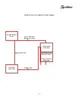
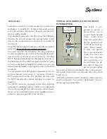
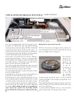
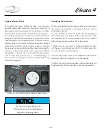
TYPICAL GALVANIC ISOLATOR
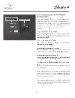
As part of the AC boat circuitry the green ground wire
takes a different path from the conductors. It enters via
the boat’s shore power inlet and travels to a galvanic iso-
lator. See the illustration.
A 60 amp (60 hertz) galvanic isolator for domestic use is
connected in series with the AC grounding “green” wire.
Overseas boats use a 30 amp (50 hertz) galvanic isolator.
The purpose of the galvanic isolator is to isolate the
boat’s grounding system
electrically from the dock
and other vessels below
1.4 volts but to maintain
a connection to the shore
green ground at high
voltage potentials. The
low voltage isolation will prevent the vessel’s zinc from
protecting the underwater metal hardware on another
vessel sharing the same AC common green ground wire.
This eliminates the possibility of galvanic interaction
from other boats on the same dock circuit and permits
your anodes to protect your boat. The green ground or
“bonding wire” runs from the boat’s shore power inlet to
a galvanic isolator stud. From the other stud of the gal-
vanic isolator it runs to the AC ground buss located be-
hind the AC main ship’s control panel in the salon. Note
that the stud nuts must be torqued and maintained at 8.8
inch pounds.
Since the galvanic isolator is not polarized either termi-
nal can be used for the inlet or outlet side for the green
grounding wire.
There is a fan located at the right side of the isolator
identified by an array of ventilation holes. If you ever
hear the fan running the
isolator has failed
. Disconnect
the shore power from the boat and check the system. Call
your closest Regal dealer for more information.
Do not store objects close to the isolator that might in-
hibit air flow to the fan.
Note that the galvanic isolator system is also used in boats
using the 50 amp main breaker (no ELCI). Normally the
galvanic isolator is found in the engine room sometimes
called the bilge or sump.
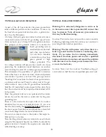
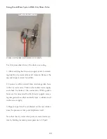
TYPICAL ISOLATOR WIRING
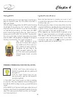
Warning: It is extremely dangerous to swim or be
in the marina water due to potential AC current that
may be present. Take all necessary precautions as
this may be life threatening.
Caution: This device does not provide a status monitor.
Following a lightning strike this unit may not continue to
provide galvanic isolation protection.
Warning: The fan will operate only when there is a
fault to ground and the isolator is conducting elec-
tricity. If you notice the fan running immediately
disconnect the shore power and contact a qualified
marine electrician to isolate and repair the problem
with the vessel or the shore power connection. Nev-
er cover the fan holes.
Caution: Never test the isolator. Troubleshooting gal-
vanic isolators shall be done by qualified personnel only.
Summary of Contents for 26 EXPRESS
Page 1: ...OWNER S MANUAL 26 EXPRESS 26 XO 4 2019...
Page 28: ...28 Chapter 2 NAVIGATION LIGHT RULES...
Page 50: ...50 Chapter 3...
Page 51: ...51 Rules Of The Road...
Page 73: ...73 Systems TYPICAL 12 VOLT HELM SWITCH PANELS PORT SWITCH PANEL STARBOARD SWITCH PANEL...
Page 121: ...121 Systems...
Page 122: ...122 Chapter 4...
Page 123: ...123 Systems...
Page 124: ...124 Chapter 4...
Page 125: ...125 Systems...
Page 126: ...126 Chapter 4...
Page 127: ...127 Systems...
Page 128: ...128 Chapter 4...
Page 129: ...129 Systems...
Page 130: ...130 Chapter 4...
Page 153: ...153 Engine Controls REGAL 26 XO TANK LABEL...
Page 177: ...177 Engine Controls SEA STAR STEERING SYSTEM SCHEMATIC OVERVIEW...
Page 262: ...262 Chapter 8 OVERBOARD DISCHARGE PAN DRAIN TYPICAL VECTOR COMPACT AC SYSTEM AIR FILTER...
Page 275: ...275 Cosmetic Care Maintenance...
Page 294: ...294 Chapter 9 HOT WATER HEATER...
Page 298: ...298 Chapter 9 STEREO DIAGNOSTIC CHART...
Page 299: ...299 Troubleshooting STEREO DIAGNOSTIC CHART...
Page 300: ...300 Chapter 9 STEREO DIAGNOSTIC CHART...
Page 303: ...303 Troubleshooting THRUSTER BOW...
Page 304: ...304 Chapter 9 TYPICAL WINDLASS...
Page 321: ...321 Technical Information TECHNICAL DRAWINGS...
Page 325: ...Technical Information 322 26 EXPRESS GALVANIC ISOLATOR WIRING...
Page 326: ...Technical Information 323 TYPICAL NMEA 2000 NETWORK COMPONENTS...
Page 328: ...Technical Information 325 26 EXPRESS TYPICAL DC GROUND CIRCUITRY...
Page 329: ...Technical Information 326 26 EXPRESS TYPICAL TRIM TAB SWITCH CIRCUITRY...
Page 330: ...Technical Information 327 26 EXPRESS TYPICAL GFCI CIRCUITRY...
Page 331: ...Technical Information 328 26 EXPRESS TYPICAL FIRE EXTINGUISHER GROUND CIRCUITRY...
Page 332: ...Technical Information 329 26 EXPRESS TYPICAL STEREO BLUETOOTH WIRING EARLIER...
Page 333: ...Technical Information 330 26 EXPRESS TYPICAL SWITCH PANEL HARNESS PLUG CIRCUITRY...
Page 334: ...Technical Information 331 26 EXPRESS TYPICAL SWITCH PANEL CIRCUITRY...
Page 335: ...Technical Information 332 26 EXPRESS BATTERY MANAGEMENT PANEL FRONT CIRCUITRY...
Page 336: ...Technical Information 333 26 EXPRESS BATTERY MANAGEMENT PANEL REAR CIRCUITRY...
Page 337: ...Technical Information 334 26 EXPRESS DOMESTIC 120 VOLT MAIN AC PANEL...
Page 338: ...Technical Information 335 26 EXPRESS OVERSEAS 230 VOLT MAIN AC PANEL...
Page 339: ...Technical Information 336 26 EXPRESS DOMESTIC 120 VOLT MAIN AC PANEL...
Page 340: ...Technical Information 337 26 EXPRESS GALLEY ELECTRIC BREAKOUT 1...
Page 341: ...Technical Information 338 26 EXPRESS GALLEY ELECTRIC BREAKOUT 2...
Page 342: ...Technical Information 339 26 EXPRESS GALLEY ELECTRIC BREAKOUT 3...
Page 343: ...Technical Information 340 26 EXPRESS GALLEY ELECTRIC BREAKOUT 4...
Page 344: ...Technical Information 341 26 EXPRESS GALLEY ELECTRIC BREAKOUT 5...
Page 345: ...Technical Information 342 26 EXPRESS GALLEY ELECTRIC BREAKOUT 6...
Page 347: ...Technical Information 344 26 EXPRESS MACHINERY LAYOUT PROFILE VIEW EXPLODED...
Page 348: ...Technical Information 345 26 EXPRESS MACHINERY LAYOUT TOP VIEW EXPLODED...
Page 353: ...Technical Information 350 26 EXPRESS TYPICAL BOW PLAN WINDLASS...
Page 359: ...Technical Information 356...
Page 360: ...Technical Information 357...
Page 361: ...Technical Information 358...
Page 362: ...Technical Information 359...
Page 363: ...Technical Information 360...
Page 364: ...Technical Information 361...
Page 365: ...Technical Information 362...
Page 366: ...Technical Information 363...
Page 367: ...Technical Information 364...
Page 368: ...Technical Information 365...
Page 369: ...Technical Information 366...
Page 370: ...Technical Information 367...
Page 371: ...Technical Information 368...
Page 373: ...Technical Information 370...
Page 374: ...Technical Information 371...
Page 375: ...Technical Information 372...
Page 376: ...Technical Information 373...
Page 377: ...Technical Information 374...
Page 379: ...Technical Information 376...
Page 381: ...Technical Information 378...
Page 382: ...Technical Information 379...
Page 383: ...Technical Information 380...
Page 384: ...Technical Information 381...
Page 386: ...Technical Information 383...
Page 387: ...Technical Information 384...
Page 388: ...Technical Information 385...
Page 389: ...Technical Information 386...

