Systems
ª
«
¬
Fuel Gauge & Sender
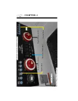
The dash fuel gauge is only an indication of the on board fuel supply.
They are not exact reading instruments. Therefore, use the one third
rule discussed earlier for monitoring your fuel supply.
There are not many
fi lling stations on the open waterways!
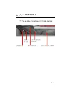
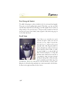
The gas sender located in the fuel
tank uses
a fl oat system which sends a signal to the dash fuel gauge as
to the fuel tank level.
Fuel filters are installed on each
outboard engine under the motor
shroud (cover) which should be
s e r v i c e d p e r o u t b o a r d m o t o r
manufacturer. Also, Regal installs for
each outboard an in-line 10 micron
water separator fi lter which is a spin
on type similar to an automobile oil
fi lter. Its main purpose is to trap dirt
particles and condensation in fuel. It is
a good idea to keep an extra fuel fi lter
on board along with a fi lter wrench,
catch container and clean rags for
emergencies. Never use automotive style fuel fi lters on your vessel.
Dispose of all fuel residue materials in an environmentally safe fashion.
In-line water separator fi lter shown above..
Fuel Filters
Summary of Contents for 29 OBX
Page 1: ...OWNER S MANUAL OWNER S MANUAL 29 OBX 29 OBX REGAL 281760 REGAL 281760 3 2016...
Page 2: ...THIS PAGE IS LEFT INTENTIONALLY BLANK...
Page 7: ...INT 7 Introduction THIS PAGE IS LEFT INTENTIONALLY BLANK...
Page 18: ...INT 18...
Page 38: ...u v u w CHAPTER 1 NAVIGATION LIGHT RULES...
Page 41: ...Safety On Board...
Page 94: ...Engine Controls 3 27 Typical Switch Shown Above...
Page 96: ...Engine Controls 3 29...
Page 162: ...Equipment Operation X Y Z Typical Dual Battery Switch Circuitry Front View...
Page 163: ...CHAPTER 6 _ Dual Battery Switch Circuitry Rear View...
Page 171: ...CHAPTER 6 CANVAS TRAVEL COVER...
Page 182: ...Equipment Operation Depth Gauge With Functions...
Page 196: ...Equipment Operation...
Page 257: ...Cosmetic Care Maintenance 7 35 Notes...
Page 262: ...Troubleshooting 8 5...
Page 263: ...CHAPTER 8 8 6...
Page 264: ...Troubleshooting 8 7...
Page 265: ...CHAPTER 8 8 8 0 1 0 2 3 4 5 6 2 4 6 7 8 9 2 3...
Page 273: ...CHAPTER 9 Notes...
Page 294: ...Technical Information 12 3 TYPICAL LABELS LOCATIONS Power Tower...
Page 299: ...Technical Information...
Page 305: ...Technical Information Note Locate per Splash...
Page 306: ...Technical Information...
Page 310: ...Technical Information TYPICAL HULL HARNESS BREAKOUT...
Page 311: ...Technical Information TYPICAL SWITCH PANEL BREAKOUT...
Page 312: ...Technical Information TYPICAL DASH CHARTPLOTTER BREAKOUT...
Page 313: ...Technical Information TYPICAL GARMIN YAMAHA NEMA 2000 NETWORK...
Page 324: ...Technical Information...

