CHAPTER 6
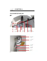
M
N
O
P
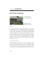
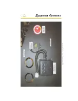
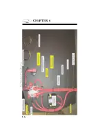
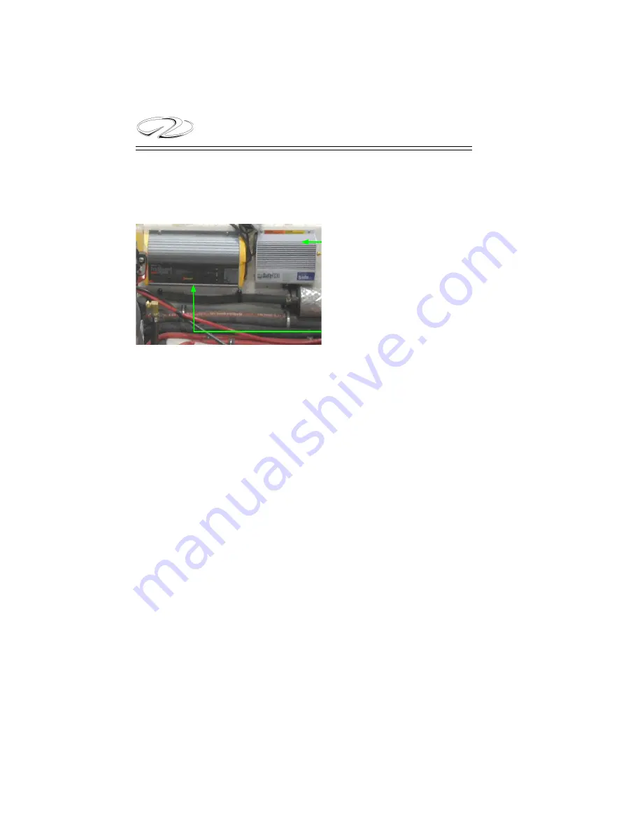
30 AMP GALVANIC
ISOLATOR (TYPICAL)
Overview
An optional 30 amp battery charger may be installed on your vessel. It
features digital microprocessor charging technology, 15 amp grounded
receptacle and a galvanic isolator. Other features include digital bank
trouble indicators, monthly storage reconditioning mode and digital
LED display (LED’s for operation status and trouble-shooting). Use
the battery charging system at dockside by plugging in an approved
extension cord as indicated in the next page warning. The available
current will be able to support on board components such as cockpit
refrigerator, stereo system, cockpit heater along with any electronics
including gaming devices.
Role Of Galvanic Isolator
The galvanic isolator is 30 amps and it is part of the battery charger
option. Technically speaking the galvanic isolator blocks DC current
fl ow on the grounding circuit (in the case of the 29 OBX it would
involve the green ground wire/round connector on a 3 prong extension
cord; male end). The system minimizes the possibility of electrocution.
30 AMP BATTERY
CHARGER (TYPICAL)
BATTERY CHARGER
Summary of Contents for 29 OBX
Page 1: ...OWNER S MANUAL OWNER S MANUAL 29 OBX 29 OBX REGAL 281760 REGAL 281760 3 2016...
Page 2: ...THIS PAGE IS LEFT INTENTIONALLY BLANK...
Page 7: ...INT 7 Introduction THIS PAGE IS LEFT INTENTIONALLY BLANK...
Page 18: ...INT 18...
Page 38: ...u v u w CHAPTER 1 NAVIGATION LIGHT RULES...
Page 41: ...Safety On Board...
Page 94: ...Engine Controls 3 27 Typical Switch Shown Above...
Page 96: ...Engine Controls 3 29...
Page 162: ...Equipment Operation X Y Z Typical Dual Battery Switch Circuitry Front View...
Page 163: ...CHAPTER 6 _ Dual Battery Switch Circuitry Rear View...
Page 171: ...CHAPTER 6 CANVAS TRAVEL COVER...
Page 182: ...Equipment Operation Depth Gauge With Functions...
Page 196: ...Equipment Operation...
Page 257: ...Cosmetic Care Maintenance 7 35 Notes...
Page 262: ...Troubleshooting 8 5...
Page 263: ...CHAPTER 8 8 6...
Page 264: ...Troubleshooting 8 7...
Page 265: ...CHAPTER 8 8 8 0 1 0 2 3 4 5 6 2 4 6 7 8 9 2 3...
Page 273: ...CHAPTER 9 Notes...
Page 294: ...Technical Information 12 3 TYPICAL LABELS LOCATIONS Power Tower...
Page 299: ...Technical Information...
Page 305: ...Technical Information Note Locate per Splash...
Page 306: ...Technical Information...
Page 310: ...Technical Information TYPICAL HULL HARNESS BREAKOUT...
Page 311: ...Technical Information TYPICAL SWITCH PANEL BREAKOUT...
Page 312: ...Technical Information TYPICAL DASH CHARTPLOTTER BREAKOUT...
Page 313: ...Technical Information TYPICAL GARMIN YAMAHA NEMA 2000 NETWORK...
Page 324: ...Technical Information...

