Equipment Operation
&
'
(
)
If the red LED begins to glow softly and or intermittently, it is an
indication that the gasoline vapor build-up is beginning to occur and
you can anticipate a full alarm momentarily. Immediately have all
passengers and crew exit the passenger compartment. If an explosion
or
fi re should occur, the probability of injury will be greatly reduced
if no one is in a confi ned area of the vessel.
NOTE: IT IS IMPORTANT TO UNDERSTAND THAT AN
ALARM WOULD NOT OCCUR UNLESS A PROBLEM EXISTED.
CAREFULLY CHECK ALL FUEL LINES, GAS LINES, AND ANY
OTHER POTENTIAL SOURCES OF GAS LEAKS.
IN THE EVENT OF AN ALARM:
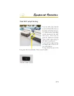
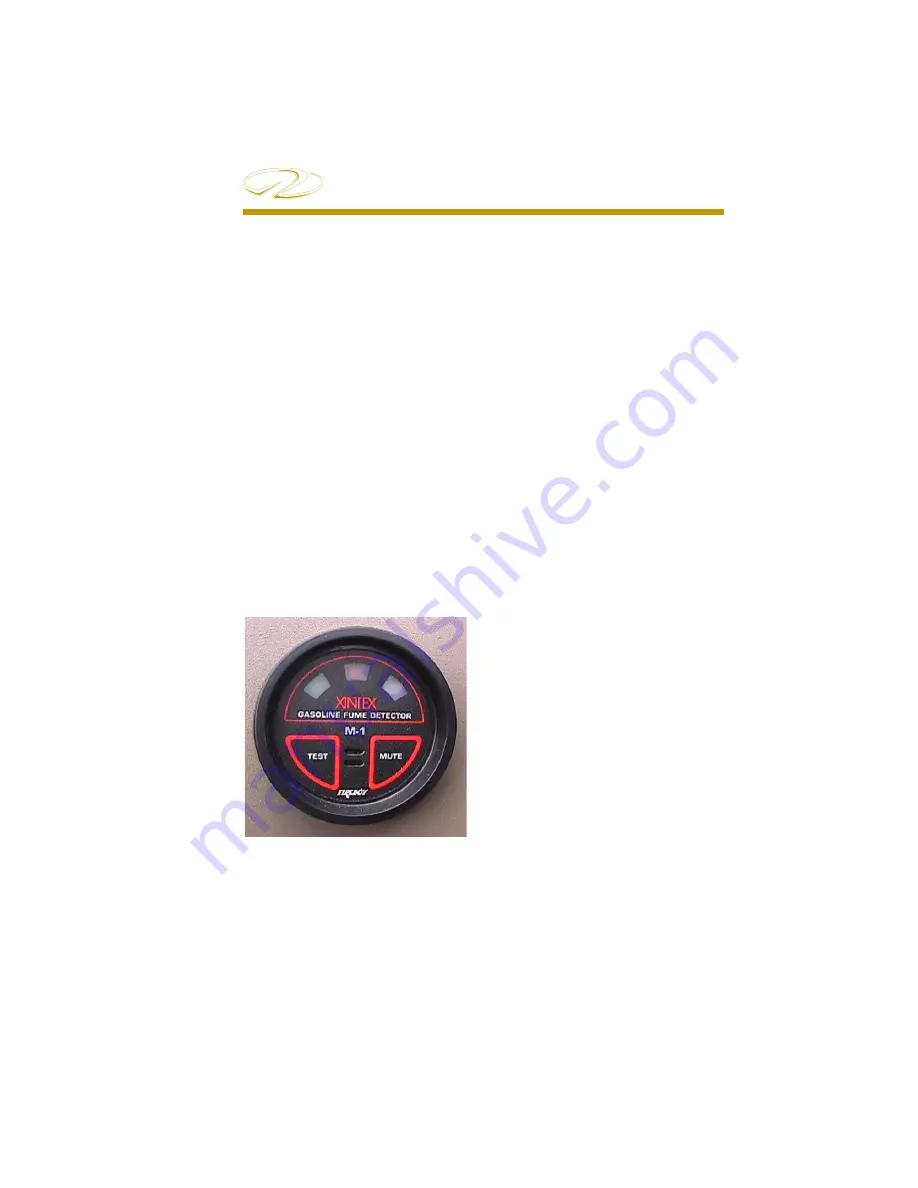
Testing System
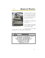
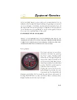
The head unit can be tested for
electrical continuity by pressing
the “Test” switch. The Red LED
will come on. The light will glow as
long as the switch is held down. If
the test switch is held down longer
than 10 seconds the horn will sound
and the “MUTE” switch must be
pushed to silence the horn.
Unplug the sensor wire from the
helm display head while the unit
is powered up. The Red LED will
illuminate and within 10-15 seconds the alarm horn will sound. If
warning Red LED fails to come on & horn fails to sound, remove
display head & return to factory for repair.
Summary of Contents for 29 OBX
Page 1: ...OWNER S MANUAL OWNER S MANUAL 29 OBX 29 OBX REGAL 281760 REGAL 281760 3 2016...
Page 2: ...THIS PAGE IS LEFT INTENTIONALLY BLANK...
Page 7: ...INT 7 Introduction THIS PAGE IS LEFT INTENTIONALLY BLANK...
Page 18: ...INT 18...
Page 38: ...u v u w CHAPTER 1 NAVIGATION LIGHT RULES...
Page 41: ...Safety On Board...
Page 94: ...Engine Controls 3 27 Typical Switch Shown Above...
Page 96: ...Engine Controls 3 29...
Page 162: ...Equipment Operation X Y Z Typical Dual Battery Switch Circuitry Front View...
Page 163: ...CHAPTER 6 _ Dual Battery Switch Circuitry Rear View...
Page 171: ...CHAPTER 6 CANVAS TRAVEL COVER...
Page 182: ...Equipment Operation Depth Gauge With Functions...
Page 196: ...Equipment Operation...
Page 257: ...Cosmetic Care Maintenance 7 35 Notes...
Page 262: ...Troubleshooting 8 5...
Page 263: ...CHAPTER 8 8 6...
Page 264: ...Troubleshooting 8 7...
Page 265: ...CHAPTER 8 8 8 0 1 0 2 3 4 5 6 2 4 6 7 8 9 2 3...
Page 273: ...CHAPTER 9 Notes...
Page 294: ...Technical Information 12 3 TYPICAL LABELS LOCATIONS Power Tower...
Page 299: ...Technical Information...
Page 305: ...Technical Information Note Locate per Splash...
Page 306: ...Technical Information...
Page 310: ...Technical Information TYPICAL HULL HARNESS BREAKOUT...
Page 311: ...Technical Information TYPICAL SWITCH PANEL BREAKOUT...
Page 312: ...Technical Information TYPICAL DASH CHARTPLOTTER BREAKOUT...
Page 313: ...Technical Information TYPICAL GARMIN YAMAHA NEMA 2000 NETWORK...
Page 324: ...Technical Information...

