CHAPTER 2
2-6
NAVIGATION AIDS
Navigation aids are placed along coasts and navigable waters as a guide
for mariners in determining their position in reference to land and
hidden danger. Each aid provides specifi c information. They form a
continuous system of charted markers for accurate piloting on paper
and on the water.
Nautical charts are provided by the National Ocean Service (NOS)
and are distributed nationwide through marinas and outlet stores.
These charts show the geography of the coast, water depth, landmarks,
navigation aids (buoys and markers), marine hazards, and port facilities.
Use only up-to-date charts for navigation. We recommend when
purchasing a chart to look for the weather resistant ones.
Buoys provide a road map to keep the skipper on course and to avoid
hazards. Buoys are identifi ed by light, shape, color and in severe weather
conditions by sound.
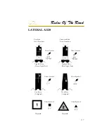
Buoys or beacons called lateral markers indicate the port and starboard
sides of the waterway to be followed. U. S markers follow the buoy
system known as Red Right Returning. When returning from sea or
traveling upstream, the green markers are to port (on your left) and the
red markers are to the starboard side (on your right). When traveling
downstream or out to sea the marker color would be reversed. The
Intercoastal waterway uses a different system of lateral markers for
port and starboard. Before operating your vessel, learn to identify the
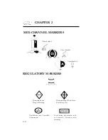
various navigational aids such as lateral aids, mid-channel markers,
information and regulatory markers.
!
"
#
$
"
%
&
$
#
'
!
$
&
(
%
$
#
"
$
(
"
)
$
"
$
#
*
+
,
(
"
)
-
$
#
.
"
$
#
(
#
.
,
(
+
(
-
"
$
#
-
(
#
(
%
"
(
'
!
$
&
$
"
$
#
/
#
+
"
!
"
$
(
'
!
$
&
/
"
%
%
0
(
%
(
#
.
1
"
%
&
.
(
#
0
$
!
*
Summary of Contents for 29 OBX
Page 1: ...OWNER S MANUAL OWNER S MANUAL 29 OBX 29 OBX REGAL 281760 REGAL 281760 3 2016...
Page 2: ...THIS PAGE IS LEFT INTENTIONALLY BLANK...
Page 7: ...INT 7 Introduction THIS PAGE IS LEFT INTENTIONALLY BLANK...
Page 18: ...INT 18...
Page 38: ...u v u w CHAPTER 1 NAVIGATION LIGHT RULES...
Page 41: ...Safety On Board...
Page 94: ...Engine Controls 3 27 Typical Switch Shown Above...
Page 96: ...Engine Controls 3 29...
Page 162: ...Equipment Operation X Y Z Typical Dual Battery Switch Circuitry Front View...
Page 163: ...CHAPTER 6 _ Dual Battery Switch Circuitry Rear View...
Page 171: ...CHAPTER 6 CANVAS TRAVEL COVER...
Page 182: ...Equipment Operation Depth Gauge With Functions...
Page 196: ...Equipment Operation...
Page 257: ...Cosmetic Care Maintenance 7 35 Notes...
Page 262: ...Troubleshooting 8 5...
Page 263: ...CHAPTER 8 8 6...
Page 264: ...Troubleshooting 8 7...
Page 265: ...CHAPTER 8 8 8 0 1 0 2 3 4 5 6 2 4 6 7 8 9 2 3...
Page 273: ...CHAPTER 9 Notes...
Page 294: ...Technical Information 12 3 TYPICAL LABELS LOCATIONS Power Tower...
Page 299: ...Technical Information...
Page 305: ...Technical Information Note Locate per Splash...
Page 306: ...Technical Information...
Page 310: ...Technical Information TYPICAL HULL HARNESS BREAKOUT...
Page 311: ...Technical Information TYPICAL SWITCH PANEL BREAKOUT...
Page 312: ...Technical Information TYPICAL DASH CHARTPLOTTER BREAKOUT...
Page 313: ...Technical Information TYPICAL GARMIN YAMAHA NEMA 2000 NETWORK...
Page 324: ...Technical Information...

