Engine & Controls
3-3
• Check po
wer trim fl uid.
At Helm/ Deck
• Check power trim for operation.
• Check control lever for operational defects. Check the clip and
safety lanyard for functionality.
• Check gauges for accuracy.
• Check fuel level and ensure the level is suffi cient for the trip with
a reserve.
ENGINE COOLING SYSTEM
Your typical engine normally utilizes a raw water system for cooling
the engine with intakes at the gearcase. It is important that this
system continues to run unobstrucrted at all times to avoid hazardous
situations and to ensure a safe voyage.
Raw water is drawn up into the outboard vertical driveshaft housing
through pick-up feeds in the gearcase vicinity. Water passes through
a powerhead thermostat which controls how much water circulates
through the powerhead. The cool water absorbs heat produced by the
engine, before being emitted via the coolant exhaust system.T
There is a access hole on the port side of the powerhead which shows
a visual stream of water at all times. If no water is visible with the
engine running shut down the engine and investigate the problem. At
times this relief hole can be plugged by debris.
Summary of Contents for 29 OBX
Page 1: ...OWNER S MANUAL OWNER S MANUAL 29 OBX 29 OBX REGAL 281760 REGAL 281760 3 2016...
Page 2: ...THIS PAGE IS LEFT INTENTIONALLY BLANK...
Page 7: ...INT 7 Introduction THIS PAGE IS LEFT INTENTIONALLY BLANK...
Page 18: ...INT 18...
Page 38: ...u v u w CHAPTER 1 NAVIGATION LIGHT RULES...
Page 41: ...Safety On Board...
Page 94: ...Engine Controls 3 27 Typical Switch Shown Above...
Page 96: ...Engine Controls 3 29...
Page 162: ...Equipment Operation X Y Z Typical Dual Battery Switch Circuitry Front View...
Page 163: ...CHAPTER 6 _ Dual Battery Switch Circuitry Rear View...
Page 171: ...CHAPTER 6 CANVAS TRAVEL COVER...
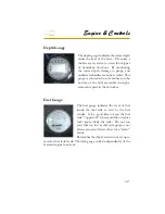
Page 182: ...Equipment Operation Depth Gauge With Functions...
Page 196: ...Equipment Operation...
Page 257: ...Cosmetic Care Maintenance 7 35 Notes...
Page 262: ...Troubleshooting 8 5...
Page 263: ...CHAPTER 8 8 6...
Page 264: ...Troubleshooting 8 7...
Page 265: ...CHAPTER 8 8 8 0 1 0 2 3 4 5 6 2 4 6 7 8 9 2 3...
Page 273: ...CHAPTER 9 Notes...
Page 294: ...Technical Information 12 3 TYPICAL LABELS LOCATIONS Power Tower...
Page 299: ...Technical Information...
Page 305: ...Technical Information Note Locate per Splash...
Page 306: ...Technical Information...
Page 310: ...Technical Information TYPICAL HULL HARNESS BREAKOUT...
Page 311: ...Technical Information TYPICAL SWITCH PANEL BREAKOUT...
Page 312: ...Technical Information TYPICAL DASH CHARTPLOTTER BREAKOUT...
Page 313: ...Technical Information TYPICAL GARMIN YAMAHA NEMA 2000 NETWORK...
Page 324: ...Technical Information...

