3
Systems
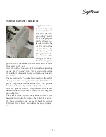
The battery charger is located in the engine room. Its
function is to keep the batteries fully charged, to provide
engine starting power and house D.C. circuit energy.
The
battery charger operates on 120 volt A.C. shore power to
provide the A.C. source for the battery charger to
function.
At the ship’s main A.C. panel the battery charger breaker
needs to be energized for the batteries to be charged from
dockside. The battery charger is a self-limiting device
which means the charger output remains at a value that
will not damage the charger if a short circuit develops at
the D.C. output terminals over a specified period of time.
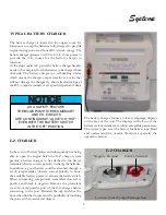
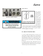
TYPICAL BATTERY CHARGER
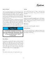
NOTICE
AS A SAFETY FEATURE
THE BILGE PUMP, STEREO MEMORY
AND CO CIRCUITS
ARE CONTINUOUSLY “ALIVE” OR “HOT”
EVEN WITH THE BATTERY SWITCH
IN THE “OFF” POSITION.
The battery charger features volt and amperage displays
on the face of the unit. The displays will tell you if the
battery system numbers are within acceptable parameters.
The system is pre-set at the factory for battery type. Read
and understand the vendor literature especially the
operation section.
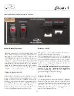
E-Z CHARGER
E-Z CHARGER
Positive Terminal
Negative Terminal
In the event of battery failure and subsequently not being
able to open the engine hatch the E-Z charge system
permits a battery charger to be attached to the device
terminals (observe correct polarity) to charge the batteries.
In addition, a good battery could be attached through a
set of jumper cables (observe correct polarity) to boost
the available battery power to actuate the hatch switch.
When connecting components remember that red is
positive and black is negative. Remove the protectant
cover from the positive post of the E-Z charger before
connecting to the post. Reinstall the cap and shut the
door when finished to prevent the possibility of touching
the posts with stored metal objects.
Location- Under Cockpit Passenger Seat
Summary of Contents for 30 EXPRESS
Page 1: ...30 EXPRESS OWNER S MANUAL...
Page 2: ...784022 OWNER S MANUAL 30 EXPRESS 12 2012...
Page 30: ...11 Safety On Board NAVIGATION LIGHT RULES...
Page 41: ...Chapter 2 22 Notes...
Page 44: ...3 Rules Of The Road NAVIGATION RULES...
Page 85: ...28 Chapter 5 Notes...
Page 105: ...4 Chapter 7...
Page 106: ...5 Equipment Operation...
Page 107: ...6 Chapter 7...
Page 108: ...7 Equipment Operation...
Page 109: ...8 Chapter 7...
Page 110: ...9 Equipment Operation...
Page 111: ...10 Chapter 7...
Page 117: ...16 Chapter 7...
Page 126: ...25 Equipment Operation ROTARY ENCODER AND MENU KEY...
Page 127: ...26 Chapter 7 USING THE ROTARY ENCODER AND MENU KEY...
Page 158: ...57 Equipment Operation BACKING A TRAILER 1 2 3 4 LAUNCHING RAMP...
Page 161: ...60 Chapter 7 Notes...
Page 195: ...34 Chapter 8 Notes...
Page 204: ...9 Troubleshooting TOILET SYSTEM DIAGNOSTIC CHART...
Page 209: ...14 Chapter 9...
Page 219: ...6 Chapter 11 Notes...
Page 221: ...2 Chapter 12...
Page 224: ...5 Technical Information 30 Express Deck Overview 30 Express Cabin Overview...
Page 225: ...Technical Information 12 6 30 EXPRESS...
Page 226: ...12 7 Technical Information 30 EXPRESS...
Page 227: ...Technical Information 12 8 30 EXPRESS...
Page 228: ...12 9 Technical Information 30 EXPRESS...
Page 229: ...Technical Information 12 10 30 EXPRESS 30 EXPRESS...
Page 230: ...12 11 Technical Information TYPICAL NEGATIVE GROUND SYSTEM...
Page 231: ...Technical Information 12 12 30 EXPRESS...
Page 232: ...12 13 Technical Information 30 EXPRESS...

