9
Systems
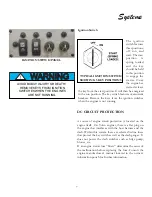
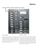
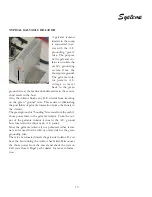
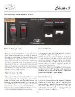
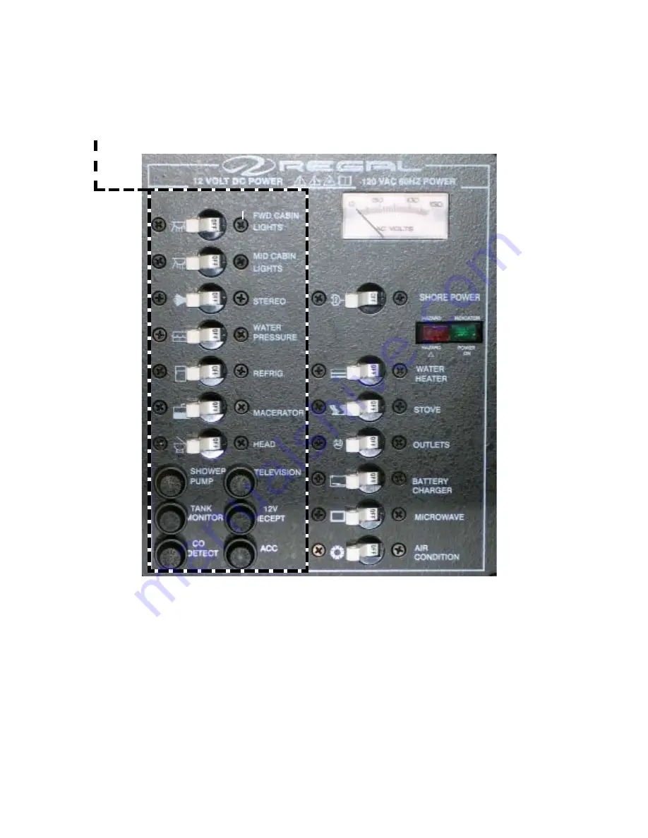
MAIN D.C.PANEL (TYPICAL) SWITCH FUNCTIONS
Typical D.C. Switches
The D.C. switches control various equipment functions
on the vessel. By activating each switch you will be able
to determine its corresponding shore power breaker.
Upon leaving the vessel turn all switches and breakers to
the “off ” position. If a breaker “pops” due to an overload
it will assume a “middle of the road” position until the
thermocouple cools down and it can be reset. Always
determine the cause of an overload and repair the problem
before trying to reset the breaker.
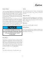
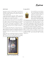
D.C. Line Voltage
The D.C. line voltage indicates current battery voltage.
Normal readings should be above 12 volts although it is
not abnormal for the meter to fluxuate somewhat. As D.C.
equipment is activated the volt meter will indicate a slight
change in meter readings. With the battery switches in the
off position upon leaving the vessel the meter will not
indicate any voltage. This is normal.
DC EQUIPMENT BREAKERS/SWITCHES
15
BKR. AMPERAGE
10
15
15
10
30
10
5
2.5
2.5
10
15
15
Summary of Contents for 30 EXPRESS
Page 1: ...30 EXPRESS OWNER S MANUAL...
Page 2: ...784022 OWNER S MANUAL 30 EXPRESS 12 2012...
Page 30: ...11 Safety On Board NAVIGATION LIGHT RULES...
Page 41: ...Chapter 2 22 Notes...
Page 44: ...3 Rules Of The Road NAVIGATION RULES...
Page 85: ...28 Chapter 5 Notes...
Page 105: ...4 Chapter 7...
Page 106: ...5 Equipment Operation...
Page 107: ...6 Chapter 7...
Page 108: ...7 Equipment Operation...
Page 109: ...8 Chapter 7...
Page 110: ...9 Equipment Operation...
Page 111: ...10 Chapter 7...
Page 117: ...16 Chapter 7...
Page 126: ...25 Equipment Operation ROTARY ENCODER AND MENU KEY...
Page 127: ...26 Chapter 7 USING THE ROTARY ENCODER AND MENU KEY...
Page 158: ...57 Equipment Operation BACKING A TRAILER 1 2 3 4 LAUNCHING RAMP...
Page 161: ...60 Chapter 7 Notes...
Page 195: ...34 Chapter 8 Notes...
Page 204: ...9 Troubleshooting TOILET SYSTEM DIAGNOSTIC CHART...
Page 209: ...14 Chapter 9...
Page 219: ...6 Chapter 11 Notes...
Page 221: ...2 Chapter 12...
Page 224: ...5 Technical Information 30 Express Deck Overview 30 Express Cabin Overview...
Page 225: ...Technical Information 12 6 30 EXPRESS...
Page 226: ...12 7 Technical Information 30 EXPRESS...
Page 227: ...Technical Information 12 8 30 EXPRESS...
Page 228: ...12 9 Technical Information 30 EXPRESS...
Page 229: ...Technical Information 12 10 30 EXPRESS 30 EXPRESS...
Page 230: ...12 11 Technical Information TYPICAL NEGATIVE GROUND SYSTEM...
Page 231: ...Technical Information 12 12 30 EXPRESS...
Page 232: ...12 13 Technical Information 30 EXPRESS...

