17
Systems
REVERSE
POLARITY
Reverse Polarity
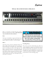
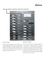
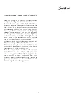
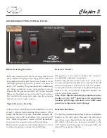
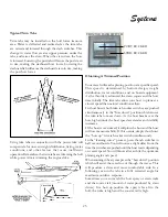
The reverse polarity indicator icon on the main panel uses
green and red lights. With the shore power cord in place
and the shore power main breaker in the “off ” position
the light will indicate green or red. As with a traffic light
green is go and on board the vessel it means the power is
connected properly. At this point the main shore power
breaker can be activated.
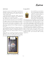
If the reverse polarity indicator on the shorepower panel
shows red the hot conductor wire is reversed at some point.
Do not attempt to energize the shore power main breaker
at this point. Disconnect the shore power cord from the
dockside receptacle. There may be a problem with the
dockside wiring. Contact the appropriate personnel.
Outlets
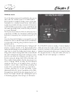
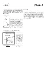
This switch controls the A.C. outlets in the salon, head
forward and aft cabins. These outlets are all GFCI
protected.
Battery Charger
This switch controls alternating current to the battery
charger located in the bilge. When leaving the vessel the
battery charger breaker should be activated to keep the
batteries charged.
Microwave
This switch controls the galley microwave.
Air Conditioner
This switch controls the air conditioner located in the
main cabin. This breaker allows power to the A/C monitor
panel located in the salon.
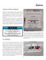
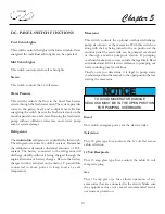
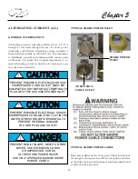
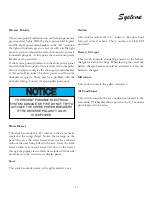
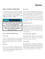
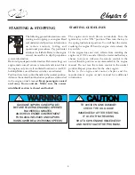
TO PREVENT POSSIBLE ELECTRICAL
SYSTEM DAMAGE OR FIRE DO NOT TRY TO
ACTIVATE THE SHORE POWER BREAKERS
IF THE REVERSE POLARITY LIGHT
IS DISPLAYED.
NOTICE
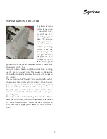
Water Heater
This switch controls the A.C. current to the water heater
located in the sump (bilge). Notice the warning on the
panel that says the water heater must not be activated
without the unit being filled with water. Once the fresh
water switch is activated water will flow to the heater
through the piping via the fresh water tank which can be
monitored on the water/waste display panel.
Stove
This switch controls power to the galley electric stove.
Summary of Contents for 30 EXPRESS
Page 1: ...30 EXPRESS OWNER S MANUAL...
Page 2: ...784022 OWNER S MANUAL 30 EXPRESS 12 2012...
Page 30: ...11 Safety On Board NAVIGATION LIGHT RULES...
Page 41: ...Chapter 2 22 Notes...
Page 44: ...3 Rules Of The Road NAVIGATION RULES...
Page 85: ...28 Chapter 5 Notes...
Page 105: ...4 Chapter 7...
Page 106: ...5 Equipment Operation...
Page 107: ...6 Chapter 7...
Page 108: ...7 Equipment Operation...
Page 109: ...8 Chapter 7...
Page 110: ...9 Equipment Operation...
Page 111: ...10 Chapter 7...
Page 117: ...16 Chapter 7...
Page 126: ...25 Equipment Operation ROTARY ENCODER AND MENU KEY...
Page 127: ...26 Chapter 7 USING THE ROTARY ENCODER AND MENU KEY...
Page 158: ...57 Equipment Operation BACKING A TRAILER 1 2 3 4 LAUNCHING RAMP...
Page 161: ...60 Chapter 7 Notes...
Page 195: ...34 Chapter 8 Notes...
Page 204: ...9 Troubleshooting TOILET SYSTEM DIAGNOSTIC CHART...
Page 209: ...14 Chapter 9...
Page 219: ...6 Chapter 11 Notes...
Page 221: ...2 Chapter 12...
Page 224: ...5 Technical Information 30 Express Deck Overview 30 Express Cabin Overview...
Page 225: ...Technical Information 12 6 30 EXPRESS...
Page 226: ...12 7 Technical Information 30 EXPRESS...
Page 227: ...Technical Information 12 8 30 EXPRESS...
Page 228: ...12 9 Technical Information 30 EXPRESS...
Page 229: ...Technical Information 12 10 30 EXPRESS 30 EXPRESS...
Page 230: ...12 11 Technical Information TYPICAL NEGATIVE GROUND SYSTEM...
Page 231: ...Technical Information 12 12 30 EXPRESS...
Page 232: ...12 13 Technical Information 30 EXPRESS...

