CHAPTER 6
6-38
Immediately have all passengers and crew exit the passenger
compartment. If an explosion or
fi
re should occur, the probability of
injury will be greatly reduced if no one is in a con
fi
ned area of the
vessel.
NOTE: IT IS IMPORTANT TO UNDERSTAND THAT AN
ALARM WOULD NOT OCCUR UNLESS A PROBLEM EXISTED.
CAREFULLY CHECK ALL FUEL LINES, GAS LINES, AND ANY
OTHER POTENTIAL SOURCES OF GAS LEAKS.
IN THE EVENT OF AN ALARM:
Testing System
The head unit can be tested for
electrical continuity by pressing
the “Test” switch. The Red LED
will come on. The light will glow as
long as the switch is held down. If
the test switch is held down longer
than 10 seconds the horn will sound
and the “MUTE” switch must be
pushed to silence the horn.
Unplug the sensor wire from the
helm display head while the unit
is powered up. The Red LED will
illluminate and within 10-15 seconds the alarm horn will sound. If
warning Red LED fails to come on & horn fails to sound, remove
display head & return to factory for repair.
Summary of Contents for 3200 Bowrider
Page 1: ...INT 1 OWNER S MANUAL 3200...
Page 2: ...REGAL 321302 3200 Bowrider OWNER S MANUAL 10 2012...
Page 7: ...INT 7 Introduction THIS PAGE IS LEFT INTENTIONALLY BLANK...
Page 18: ...INT 18...
Page 38: ...1 16 CHAPTER 1 NAVIGATION LIGHT RULES...
Page 41: ...1 19 Safety On Board...
Page 109: ...Vessel Operation 5 9...
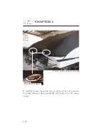
Page 150: ...CHAPTER 6 6 18 Canvas Typical PowerTower In Up Position w Sunshades...
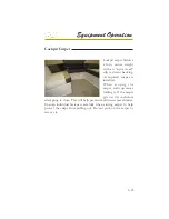
Page 155: ...Equipment Operation 6 23 Canvas Typical Storage Mooring Cover...
Page 182: ...CHAPTER 6 6 50 Typical Hinged Power Tower Actuator Hydraulic Ram Typical Power Tower...
Page 191: ...Equipment Operation 6 59...
Page 192: ...CHAPTER 6 6 60...
Page 193: ...Equipment Operation 6 61...
Page 194: ...CHAPTER 6 6 62...
Page 195: ...Equipment Operation 6 63...
Page 196: ...CHAPTER 6 6 64...
Page 197: ...Equipment Operation 6 65...
Page 199: ...Equipment Operation 6 67...
Page 200: ...CHAPTER 6 6 68...
Page 278: ...CHAPTER 9 Notes...
Page 290: ...11 4 TYPICAL LABEL PLACARD LOCATION PowerTower...
Page 292: ...6 3200 BOW RIDER DECK HARDWARE 1 0F 2...
Page 297: ...11 3200 BOW RIDER TYPICAL EPA COMPLIANT FUEL TANK INSTALLATION...
Page 299: ...13 3200 BOW RIDER COLD WATER SYSTEM RUNS...
Page 300: ...14 3200 BOW RIDER ELECTRIC TOILET W OVERBOARD DISCHARGE...
Page 301: ...15 3200 BOW RIDER ELECTRIC TOILET W DECK PUMP OUT...
Page 306: ...3200 BOW RIDER DC HEAD PANEL 20...
Page 307: ...3200 BOW RIDER HELM SWITCH PANEL 21...
Page 308: ...3200 BOW RIDER HELM BREAKER PANEL 22...
Page 309: ...3200 BOW RIDER VOLVO IGN MERC ANALOG EVC 23...
Page 310: ...3200 BOW RIDER IPA VOLVO MERC ANALOG 24...
Page 311: ...3200 BOW RIDER IPA VOLVO MERC ANALOG W GARMIN 25...
Page 312: ...3200 BOW RIDER BATTERY MANAGEMENT PANEL 26...
Page 313: ...3200 BOW RIDER AFT SWITCH PANEL 27...
Page 314: ...3200 BOW RIDER WINDLASS PANEL 28...
Page 315: ...3200 BOW RIDER HEIGHT DIMENSIONS 30 1 1 2 54 1 4 101 3 4 8 5 3 4 3 1 4 45 3 4 58 3 15 12...
Page 316: ...3200 BOW RIDER STANDARD SEATING POSITIONS 31...


