CHAPTER 6
6-82
Obtaining A Trimmed Postition
Your vessel will reach a planing position at a speci
fi
c speed. This speed
is determined by bottom design, weight distribution, water conditions,
and on board equipment. As the throttle is advanced the stern squats
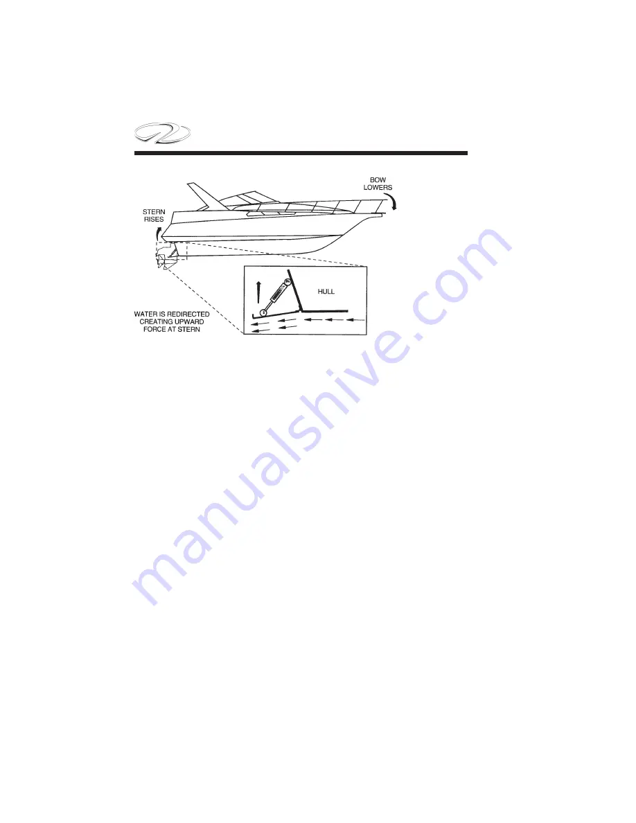
and the bow rises initially. The trim tabs allow your boat to plane at a
slower speed than natural conditions allow.
In short bursts both trim tab rocker switches are pushed simultaneously
in the “bow down” position which causes the trim tabs to move down.
As the boat breaks over the bow high attitude the boat speed accelerates
and visibility increases.
If the boat is overtrimed, it will plow the bow and the boat will lose
maneuverability. If this occurs, simply short burst the “bow up” trim
tab rocker switches simultaneously.
In the “learning curve” process, press the tab switches in half second
bursts. You will notice a slight delay from the time the switches are
pushed until the boat reacts depending on vessel speed. You will know
after awhile the optimum planing angle and speed.
When running in heavy seas press the “bow down” position which
will assist the vessel to cut through the waves. This will produce a drier
and more comfortable ride. In a following sea run the tabs in a fully
retracted angle for maximum outdrive response.
Summary of Contents for 3200 Bowrider
Page 1: ...INT 1 OWNER S MANUAL 3200...
Page 2: ...REGAL 321302 3200 Bowrider OWNER S MANUAL 10 2012...
Page 7: ...INT 7 Introduction THIS PAGE IS LEFT INTENTIONALLY BLANK...
Page 18: ...INT 18...
Page 38: ...1 16 CHAPTER 1 NAVIGATION LIGHT RULES...
Page 41: ...1 19 Safety On Board...
Page 109: ...Vessel Operation 5 9...
Page 150: ...CHAPTER 6 6 18 Canvas Typical PowerTower In Up Position w Sunshades...
Page 155: ...Equipment Operation 6 23 Canvas Typical Storage Mooring Cover...
Page 182: ...CHAPTER 6 6 50 Typical Hinged Power Tower Actuator Hydraulic Ram Typical Power Tower...
Page 191: ...Equipment Operation 6 59...
Page 192: ...CHAPTER 6 6 60...
Page 193: ...Equipment Operation 6 61...
Page 194: ...CHAPTER 6 6 62...
Page 195: ...Equipment Operation 6 63...
Page 196: ...CHAPTER 6 6 64...
Page 197: ...Equipment Operation 6 65...
Page 199: ...Equipment Operation 6 67...
Page 200: ...CHAPTER 6 6 68...
Page 278: ...CHAPTER 9 Notes...
Page 290: ...11 4 TYPICAL LABEL PLACARD LOCATION PowerTower...
Page 292: ...6 3200 BOW RIDER DECK HARDWARE 1 0F 2...
Page 297: ...11 3200 BOW RIDER TYPICAL EPA COMPLIANT FUEL TANK INSTALLATION...
Page 299: ...13 3200 BOW RIDER COLD WATER SYSTEM RUNS...
Page 300: ...14 3200 BOW RIDER ELECTRIC TOILET W OVERBOARD DISCHARGE...
Page 301: ...15 3200 BOW RIDER ELECTRIC TOILET W DECK PUMP OUT...
Page 306: ...3200 BOW RIDER DC HEAD PANEL 20...
Page 307: ...3200 BOW RIDER HELM SWITCH PANEL 21...
Page 308: ...3200 BOW RIDER HELM BREAKER PANEL 22...
Page 309: ...3200 BOW RIDER VOLVO IGN MERC ANALOG EVC 23...
Page 310: ...3200 BOW RIDER IPA VOLVO MERC ANALOG 24...
Page 311: ...3200 BOW RIDER IPA VOLVO MERC ANALOG W GARMIN 25...
Page 312: ...3200 BOW RIDER BATTERY MANAGEMENT PANEL 26...
Page 313: ...3200 BOW RIDER AFT SWITCH PANEL 27...
Page 314: ...3200 BOW RIDER WINDLASS PANEL 28...
Page 315: ...3200 BOW RIDER HEIGHT DIMENSIONS 30 1 1 2 54 1 4 101 3 4 8 5 3 4 3 1 4 45 3 4 58 3 15 12...
Page 316: ...3200 BOW RIDER STANDARD SEATING POSITIONS 31...


