Engines & Controls
3-11
Other Gauges & Indicators
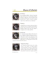
The optional gas vapor detector
determines if there is a level of
gasoline vapors that is unsafe in the
engine room of the boat. If installed,
turn on the unit and wait about one
minute for it to do its safety test. If
all is well it will dispaly a green light.
You must run the test before you start
the engines. In the event you don’t
get a green light, you must investigate
the bilge of the boat for gas fumes or
signs of a fuel leak before starting the engines. If uncertain, consult
a marine service professional
The automatic fire extinguishing
system utilizes an instrument display
unit (gauge) that provides the operator
with a system status of charged or
uncharged condition by an audible
alarm. With the ignition turned on
the indicator light shows system is
charged and operating properly. With
the ignition on and no light indicates
the system has discharged. If the
system should discharge the ignition system will be instantaneously
interrupted. Should this occur shut down the engine, ventilation blower
and any electrical system components. Investigate the source of the
shutdown immediately and take appropriate action. Also, in the cockpit
is located a manual release for the
fi
re extinguishing system. Find the
release and read the related sections in this manual along with the
vendor’s information concerning the operation of the manual release.
In case of emergency inform other crew members on the operation
of the
fi
re extinguishing system.
Summary of Contents for 3200 Bowrider
Page 1: ...INT 1 OWNER S MANUAL 3200...
Page 2: ...REGAL 321302 3200 Bowrider OWNER S MANUAL 10 2012...
Page 7: ...INT 7 Introduction THIS PAGE IS LEFT INTENTIONALLY BLANK...
Page 18: ...INT 18...
Page 38: ...1 16 CHAPTER 1 NAVIGATION LIGHT RULES...
Page 41: ...1 19 Safety On Board...
Page 109: ...Vessel Operation 5 9...
Page 150: ...CHAPTER 6 6 18 Canvas Typical PowerTower In Up Position w Sunshades...
Page 155: ...Equipment Operation 6 23 Canvas Typical Storage Mooring Cover...
Page 182: ...CHAPTER 6 6 50 Typical Hinged Power Tower Actuator Hydraulic Ram Typical Power Tower...
Page 191: ...Equipment Operation 6 59...
Page 192: ...CHAPTER 6 6 60...
Page 193: ...Equipment Operation 6 61...
Page 194: ...CHAPTER 6 6 62...
Page 195: ...Equipment Operation 6 63...
Page 196: ...CHAPTER 6 6 64...
Page 197: ...Equipment Operation 6 65...
Page 199: ...Equipment Operation 6 67...
Page 200: ...CHAPTER 6 6 68...
Page 278: ...CHAPTER 9 Notes...
Page 290: ...11 4 TYPICAL LABEL PLACARD LOCATION PowerTower...
Page 292: ...6 3200 BOW RIDER DECK HARDWARE 1 0F 2...
Page 297: ...11 3200 BOW RIDER TYPICAL EPA COMPLIANT FUEL TANK INSTALLATION...
Page 299: ...13 3200 BOW RIDER COLD WATER SYSTEM RUNS...
Page 300: ...14 3200 BOW RIDER ELECTRIC TOILET W OVERBOARD DISCHARGE...
Page 301: ...15 3200 BOW RIDER ELECTRIC TOILET W DECK PUMP OUT...
Page 306: ...3200 BOW RIDER DC HEAD PANEL 20...
Page 307: ...3200 BOW RIDER HELM SWITCH PANEL 21...
Page 308: ...3200 BOW RIDER HELM BREAKER PANEL 22...
Page 309: ...3200 BOW RIDER VOLVO IGN MERC ANALOG EVC 23...
Page 310: ...3200 BOW RIDER IPA VOLVO MERC ANALOG 24...
Page 311: ...3200 BOW RIDER IPA VOLVO MERC ANALOG W GARMIN 25...
Page 312: ...3200 BOW RIDER BATTERY MANAGEMENT PANEL 26...
Page 313: ...3200 BOW RIDER AFT SWITCH PANEL 27...
Page 314: ...3200 BOW RIDER WINDLASS PANEL 28...
Page 315: ...3200 BOW RIDER HEIGHT DIMENSIONS 30 1 1 2 54 1 4 101 3 4 8 5 3 4 3 1 4 45 3 4 58 3 15 12...
Page 316: ...3200 BOW RIDER STANDARD SEATING POSITIONS 31...


