180
Autopilot
If installed, the autopilot is part of the onboard ma-
rine network and therefore can be programmed to
maintain a course through the chartplotter route.
Easy-to-use setup provides carefree auto-guided
navigation in open waters.
Autopilot Operation
The autopilot continuously adjusts the steering on
your yacht to maintain a constant heading. The unit
can be programmed for both automatic and manu-
al steering functions and patterns.
Before using the auto pilot, be sure to read and
understand the autopilot operation manual located
in the owner’s information packet.
Follow these steps to start-up the autopilot;
1. Energize the “house” battery switch at the bat-
tery activation panel located under the cockpit
starboard cushion.
2. Press and hold the power button briefly to turn
the autopilot on or off. If the power button is re-
leased quickly instead of briefly holding it the unit
will seek the display adjustment screen verses the
main screen.
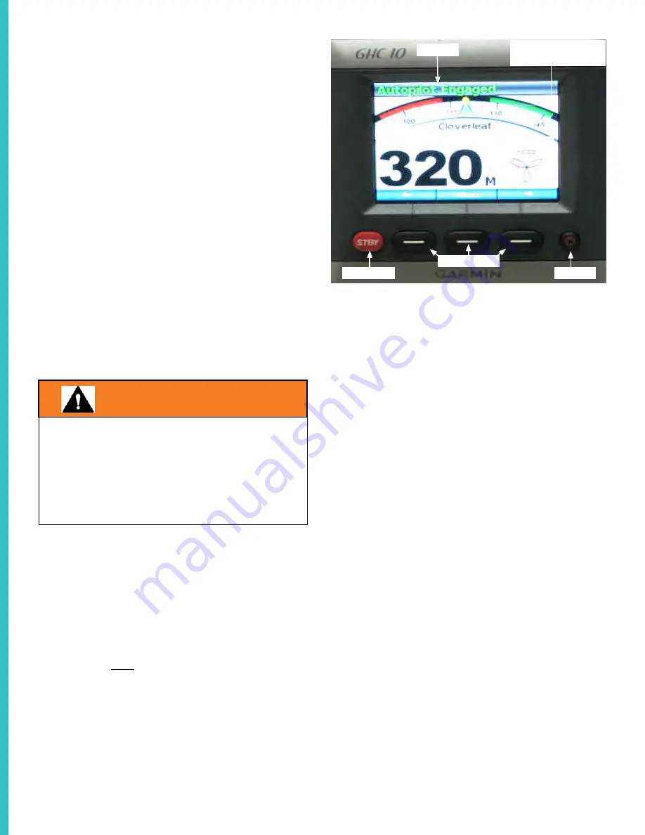
STANDBY
SOFT KEYS
POWER
STATUS
HEADING
ACTUAL HEADING
MARKER
PATTERN
General Operation Keys & Descriptions
Power- Turns the autopilot on and off.
Soft Keys- These keys help to navigate the menus,
select items, and change the autopilot steering bear-
ing. The center soft key is used to select highlighted
items and open a menu. The left soft key is used
engage the unit or to move back one screen. The
right soft key to navigate through the menu screens.
Note to press a soft key to activate the action indi-
cated directly above it.
STBY (Standby)- Press this button to start the
standby function. Press STBY to stop the autopilot
from any menu screen at any time. A time when you
use STBY might be when you are beginning your
route through a tight turning channel to a marina or
to your favorite on the water restaurant.
Note 1: When you place the autopilot in standby
mode be ready to regain manual control of the boat
steering system.
Note 2- The heading sensor is a device that is inte-
grated in the autopilot system that controls the di-
rection inputs and outputs of the unit.
TO PREVENT POSSIBLE BODILY INJURY,
DEATH OR PROPERTY DAMAGE,
NEVER LEAVE THE HELM UNATTENDED.
BE PREPARED AT ANY TIME
TO PROMPTLY REGAIN MANUAL CONTROL
OF YOUR VESSEL.
WARNING
Summary of Contents for 38 SAV 2019
Page 1: ...1 REGAL 38 SAV OWNER S MANUAL NOVEMBER 2019 EDITION...
Page 32: ...32 Navigation Light Rules...
Page 46: ...46 Navigation Rules...
Page 49: ...49 Lateral Aids...
Page 50: ...50 Channel Markers Regulatory Markers...
Page 52: ...52...
Page 53: ...53...
Page 153: ...153 Engine Starting Stopping Controls...
Page 208: ...208 TV SYSTEM COMPONENTS WIRING TV SYSTEM COMPONENTS WIRING...
Page 225: ...225 Dockside Cords...
Page 259: ...259 GENERAL ARRANGEMENTS...
Page 260: ...260 TOP VIEW...
Page 261: ...261 DOMESTIC SEATING OCCUPANCY...
Page 262: ...262 SLING LOCATIONS FOR LIFTING...
Page 265: ...265 YAMAHA OPTIMUS STEERING SYSTEM TWIN O B SHOWN...
Page 266: ...266 YAMAHA OPTIMUS FUEL HARNESS...
Page 267: ...267 GARMIN ETHERNET NETWORK NOTE GARMIN ETHERNET NETWORK LOCATED BEHIND GARMIN STBD PLOTTER...
Page 268: ...268 YAMAHA OPTIMUS NMEA NETWORK...
Page 269: ...269 AMPLIFIER SPEAKER WIRING...
Page 270: ...270 HULL HARDWARE AFT THRU HULLS...
Page 271: ...271 DECK HARDWARE OVERVIEW...
Page 272: ...272 DECK HARDWARE 1 AFT...
Page 273: ...273 DECK HARDWARE 2 BOW...
Page 274: ...274 DECK HARDWARE 4 PORT...
Page 275: ...275 DECK HARDWARE 5 TRANSOM...
Page 276: ...276 AMPLIFIER RCA WIRING SETTINGS...
Page 277: ...277 BATTERY MANAGEMENT PANEL COMPONENTS...
Page 278: ...278 BATTERY MANAGEMENT PANEL SWITCHES HARNESSES...
Page 279: ...279 BATTERY MANAGEMENT PANEL POWER CABLE OVERVIEW...
Page 280: ...280 BATTERY MANAGEMENT PANEL POWER CABLES 1...
Page 281: ...281 BATTERY MANAGEMENT PANEL POWER CABLES 2...
Page 282: ...282 BATTERY MANAGEMENT PANEL POWER CABLES 3...
Page 283: ...283 DECK HARNESS ROUTING 1...
Page 284: ...284 DECK HARNESS ROUTING 2...
Page 285: ...285 DECK HARNESS ROUTING 3...
Page 286: ...286 DECK HARNESS ROUTING 4...
Page 287: ...287 DECK HARNESS ROUTING 5...
Page 288: ...288 D C DISTRIBUTION PANEL FRONT...
Page 289: ...289 D C DISTRIBUTION PANEL REAR...
Page 290: ...290 HELM D C BREAKER PANEL FRONT...
Page 291: ...291 HELM BREAKER PANEL REAR...
Page 292: ...292 120 VOLT AC SHIP S MAIN PANEL FRONT...
Page 293: ...293 120 VOLT AC SHIP S MAIN PANEL REAR...
Page 294: ...294 SEAKEEPER WIRING...
Page 295: ...295 SUMP BILGE PUMP FLOAT SWITCH WIRING...


