52
Chapter 4
Ignition Protected Devices
Many electrical devices in everyday use tend to “arc”
or spark when being used. Th
ese include motors, fans,
switches, relays, etc.
Boats in general use many of these same devices but
they are protected from any sparking that may cause the
device to ignite with any vapors that are typically found
in the engine room and/or fuel tank compartments.
Obviously, gasoline powered vessels contain a much
higher risk of explosion over diesel powered vessels but
diesel under the right circumstances can ignite and burn.
Still when replacing any electrical device especially in the
bilge or engine room make sure it is ignition protected.
Th
is means it has been tested and normally the device
is stamped with a marking making it safe to use. Most
automotive type devices are not ignition protected
especially engine starters and alternators.
POSSIBLE PROBLEMS/SOLUTIONS (GFCI’S)
1. If the “reset” button does not pop
out, the GFCI is probably defective and
should be replaced.
2. If the “reset” button pops out one time
but tends to stick the next the GFCI
should be replaced.
3. Th
e GFCI “reset” button pops out when something is
turned on. Th
is may indicate an internal wiring prob-
lem with the GFCI or there may be a ground-fault
down stream.
4. Th
e GFCI “reset” button is in the pressed position
and nothing works. Check the appropriate breaker at
the main ship’s AC control panel to make sure it has not
“tripped” or as been deactivated.
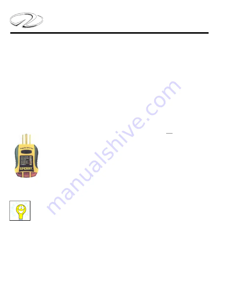
Also, GFCI down stream recep-
tacles can be tested with a plug-in
type GFCI tester. Th
is tester con-
tains a GFCI test buton which ac-
complishes the same thing as the
GFCI receptacle built-in test but-
ton. Th
is tester can be purchased at
electrical supply houses or marine
retailers.
To test a GFCI on your yacht fi nd a 120 volt night light
or small lamp to plug into the GFCI outlet. Try it in an-
other circuit fi rst to make sure it lights.
Aft er the lamp is plugged into the GFCI outlet the lamp
should light. Now press the “test” button at the GFCI
receptacle center. Th
e GFCI’s “reset” button should pop
out and the lamp should go out. Th
is means the GFCI
itself is functioning properly. Press the “reset” button
to restore power to the outlet. Test each GFCI circuit
monthly.
You can use the lamp to check receptacles down stream
from the GFCI. All receptacles should light the lamp
and should go out when the “test” button is pressed.
Testing GFCI’S
Summary of Contents for 42 Fly-Grande Coupe
Page 1: ......
Page 6: ...Table Of Contents...
Page 20: ...14 Chapter 1 Note...
Page 31: ...11 Safety On Board NAVIGATION LIGHT RULES...
Page 52: ...9 Rules Of The Road...
Page 53: ...10 Chapter 3...
Page 78: ...25 Systems TYPICAL BATTERY MANAGEMENT SYSTEM VSR...
Page 99: ...46 Chapter 4 TYPICAL AC ELCI CIRCUITRY FLOW CHART...
Page 174: ...15 Engine Controls AFT FORWARD SIDEWAYS DIAGONALLY ROTATE JOYSTICK FUNCTIONS...
Page 240: ...48 Chapter 7...
Page 241: ...49 Auxiliary Equipment Operation...
Page 242: ...50 Chapter 7 SEAKEEPER SPECIFICATIONS...
Page 281: ...35 Cosmetic Care Maintenance TYPICAL DIESEL GENERATOR PARTS DESCRIPTION...
Page 282: ...36 Chapter 8...
Page 300: ...54 Chapter 8 VOLVO IPS ENGINE DRIVE COMMON PARTS IDENTIFICATION...
Page 323: ...10 Chapter 10 SHORE CABLE SYSTEM...
Page 328: ...15 Troubleshooting TYPICAL WINDLASS...
Page 347: ...6 Chapter 13 TECHNICAL DRAWINGS...
Page 349: ...Technical Information 12 8 42 GRANDE COUPE FLY ELECTRICAL OULLETS...
Page 350: ...Technical Information 12 9 TYPICAL DC GROUND CIRCUITRY...
Page 351: ...Technical Information 12 10 TYPICAL BATTERY MANAGEMENT PANEL CIRCUITRY...
Page 352: ...Technical Information 12 11 TYPICAL GFCI CIRCUITRY...
Page 353: ...Technical Information 12 12 TYPICAL FIRE EXTINGUISHER GROUND CIRCUITRY...
Page 354: ...Technical Information 12 13 TYPICAL TWIN VOLVO DIESEL ENGINE FIRE EXT SHUTDOWN...
Page 355: ...Technical Information 12 14 TYPICAL BATTERY SWITCH CIRCUITRY...
Page 356: ...Technical Information 12 15 TYPICAL WIPER CIRCUITRY OVERVIEW...
Page 358: ...Technical Information 12 17 42 FLY UPPER HELM SWITCH PANEL...
Page 359: ...Technical Information 12 18 42 FLY UPPER HELM SWITCH PANEL...
Page 360: ...Technical Information 12 19 42 FLY UPPER HELM BREAKER PANEL...
Page 361: ...Technical Information 12 20 42 GRANDE COUPE FLY LOWER HELM SWITCH PANEL...
Page 362: ...Technical Information 12 21 42 GRANDE COUPE FLY LOWER HELM SWITCH PANEL...
Page 363: ...Technical Information 12 22 42 GRANDE COUPE FLY EUROPEAN 230 VOLT AC PANEL...
Page 364: ...Technical Information 12 23 42 GRANDE COUPE FLY EUROPEAN 230 VOLT AC PANEL AFT VIEW...
Page 365: ...Technical Information 12 24 42 GRANDE COUPE FLY 120 240 VOLT AC PANEL...
Page 366: ...Technical Information 12 25 42 GRANDE COUPE FLY 120 240 VOLT AC PANEL...
Page 367: ...Technical Information 12 26 42 GRANDE COUPE FLY 12 VOLT DC PANEL...
Page 368: ...Technical Information 12 27 42 GRANDE COUPE FLY 12 VOLT DC PANEL AFT VIEW...
Page 370: ...Technical Information 12 29 42 GRANDE COUPE FLY AIR CONDITIONING SYSTEM OVERVIEW...


