97
Systems
Your electronics package may include chartplotters,
heavy duty closed-array radar, auto pilot, sonar with
full-featured depth sounder functions, VHF radio with
DSC capability and XM satellite weather radio.
A portion of the components are optional and may not
be installed on your yacht.
Please refer to each vendors owner’s manual for in-
depth information regarding individual electronic
components.
Regal reserves the right to upgrade, change, modify, or
eliminate any system or component at anytime.
System Operation Overview
To operate the electronics the following switches need
to be activated:
1. Make sure the battery switch located inside the star-
board stairway locker is activated. To perform this func-
tion turn the “house” battery switch to the “on” position
as shown by the arrow in the illustration.
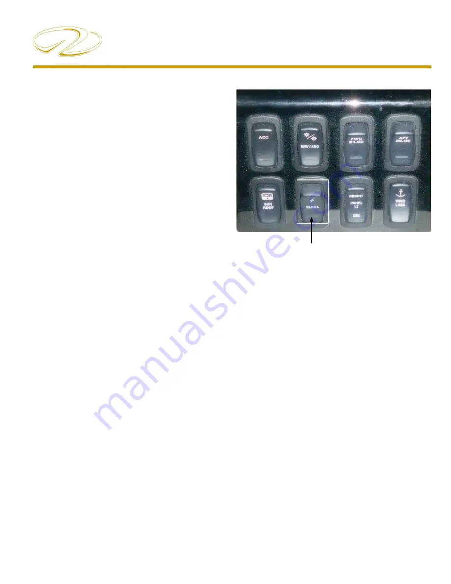
2. Activate the “electronics” switch at the helm panel
which controls power to the GPS antenna and the auto
pilot.
3. At this point each individual component can be ac-
tivated.
Refer to the illustrations for further information.
Notice the electronics switch as shown above. If the
electronics group does not power up, check to ensure
this switch is activated. Always fi nd the source of a
tripped breaker problem before reactivating it. Press the
breaker in to reset it. Note that what ever components
operate from this switch depends on each vessel’s elec-
tronics options installed.
Electronics: Helm Switch
TYPICAL ELECTRONICS OVERVIEW
Summary of Contents for 42 Fly-Grande Coupe
Page 1: ......
Page 6: ...Table Of Contents...
Page 20: ...14 Chapter 1 Note...
Page 31: ...11 Safety On Board NAVIGATION LIGHT RULES...
Page 52: ...9 Rules Of The Road...
Page 53: ...10 Chapter 3...
Page 78: ...25 Systems TYPICAL BATTERY MANAGEMENT SYSTEM VSR...
Page 99: ...46 Chapter 4 TYPICAL AC ELCI CIRCUITRY FLOW CHART...
Page 174: ...15 Engine Controls AFT FORWARD SIDEWAYS DIAGONALLY ROTATE JOYSTICK FUNCTIONS...
Page 240: ...48 Chapter 7...
Page 241: ...49 Auxiliary Equipment Operation...
Page 242: ...50 Chapter 7 SEAKEEPER SPECIFICATIONS...
Page 281: ...35 Cosmetic Care Maintenance TYPICAL DIESEL GENERATOR PARTS DESCRIPTION...
Page 282: ...36 Chapter 8...
Page 300: ...54 Chapter 8 VOLVO IPS ENGINE DRIVE COMMON PARTS IDENTIFICATION...
Page 323: ...10 Chapter 10 SHORE CABLE SYSTEM...
Page 328: ...15 Troubleshooting TYPICAL WINDLASS...
Page 347: ...6 Chapter 13 TECHNICAL DRAWINGS...
Page 349: ...Technical Information 12 8 42 GRANDE COUPE FLY ELECTRICAL OULLETS...
Page 350: ...Technical Information 12 9 TYPICAL DC GROUND CIRCUITRY...
Page 351: ...Technical Information 12 10 TYPICAL BATTERY MANAGEMENT PANEL CIRCUITRY...
Page 352: ...Technical Information 12 11 TYPICAL GFCI CIRCUITRY...
Page 353: ...Technical Information 12 12 TYPICAL FIRE EXTINGUISHER GROUND CIRCUITRY...
Page 354: ...Technical Information 12 13 TYPICAL TWIN VOLVO DIESEL ENGINE FIRE EXT SHUTDOWN...
Page 355: ...Technical Information 12 14 TYPICAL BATTERY SWITCH CIRCUITRY...
Page 356: ...Technical Information 12 15 TYPICAL WIPER CIRCUITRY OVERVIEW...
Page 358: ...Technical Information 12 17 42 FLY UPPER HELM SWITCH PANEL...
Page 359: ...Technical Information 12 18 42 FLY UPPER HELM SWITCH PANEL...
Page 360: ...Technical Information 12 19 42 FLY UPPER HELM BREAKER PANEL...
Page 361: ...Technical Information 12 20 42 GRANDE COUPE FLY LOWER HELM SWITCH PANEL...
Page 362: ...Technical Information 12 21 42 GRANDE COUPE FLY LOWER HELM SWITCH PANEL...
Page 363: ...Technical Information 12 22 42 GRANDE COUPE FLY EUROPEAN 230 VOLT AC PANEL...
Page 364: ...Technical Information 12 23 42 GRANDE COUPE FLY EUROPEAN 230 VOLT AC PANEL AFT VIEW...
Page 365: ...Technical Information 12 24 42 GRANDE COUPE FLY 120 240 VOLT AC PANEL...
Page 366: ...Technical Information 12 25 42 GRANDE COUPE FLY 120 240 VOLT AC PANEL...
Page 367: ...Technical Information 12 26 42 GRANDE COUPE FLY 12 VOLT DC PANEL...
Page 368: ...Technical Information 12 27 42 GRANDE COUPE FLY 12 VOLT DC PANEL AFT VIEW...
Page 370: ...Technical Information 12 29 42 GRANDE COUPE FLY AIR CONDITIONING SYSTEM OVERVIEW...


