44
Chapter 4
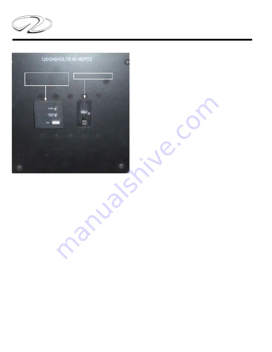
ELCI LEAKAGE FAULT DETECTOR LED
INFORMATION
As a central segment of the ELCI system there are two
LED lights with a “test” button located at the shore
power inlet. With the breaker in the ‘on” position and
the shore power cord hooked up these LED lights may
show variations in color to provide system conditions.
Th
ey are:
1. G
reen LED On- Red LED Off
Line voltage is present, the breaker is closed, and the
device is protecting the circuits against over current and
leakage current.
2. Green LED Off , Red LED On
Th
e device has detected leakage current and has opened
the circuit breaker.
3. G
reen LED fl ashing, Red LED Off
Th
e circuit breaker has opened due to overcurrent or
has been manually turned to the “off ” position.
4. Green LED Off , Red LED Off
Line voltage is not present. Check cord connections and
marina breaker for “on” position.
5. Green LED fl ashing, Red LED Off , Amber LED On
Indicates hot and neutral are reversed and the circuit
breaker is open.
Note: Check circuit at least monthly by pushing in
the white switch marked TEST. When depressed, the
breaker should return to the reset position indicating
the ELCI circuit is operating properly.
For further infomation on the ELCI PC-S refer to the
Carling web-site. Both shore power 1 and 2 use the
same testing procedure.
LEAKAGE FAULT
DETECTOR
ELCI BREAKER
Summary of Contents for 42 Fly-Grande Coupe
Page 1: ......
Page 6: ...Table Of Contents...
Page 20: ...14 Chapter 1 Note...
Page 31: ...11 Safety On Board NAVIGATION LIGHT RULES...
Page 52: ...9 Rules Of The Road...
Page 53: ...10 Chapter 3...
Page 78: ...25 Systems TYPICAL BATTERY MANAGEMENT SYSTEM VSR...
Page 99: ...46 Chapter 4 TYPICAL AC ELCI CIRCUITRY FLOW CHART...
Page 174: ...15 Engine Controls AFT FORWARD SIDEWAYS DIAGONALLY ROTATE JOYSTICK FUNCTIONS...
Page 240: ...48 Chapter 7...
Page 241: ...49 Auxiliary Equipment Operation...
Page 242: ...50 Chapter 7 SEAKEEPER SPECIFICATIONS...
Page 281: ...35 Cosmetic Care Maintenance TYPICAL DIESEL GENERATOR PARTS DESCRIPTION...
Page 282: ...36 Chapter 8...
Page 300: ...54 Chapter 8 VOLVO IPS ENGINE DRIVE COMMON PARTS IDENTIFICATION...
Page 323: ...10 Chapter 10 SHORE CABLE SYSTEM...
Page 328: ...15 Troubleshooting TYPICAL WINDLASS...
Page 347: ...6 Chapter 13 TECHNICAL DRAWINGS...
Page 349: ...Technical Information 12 8 42 GRANDE COUPE FLY ELECTRICAL OULLETS...
Page 350: ...Technical Information 12 9 TYPICAL DC GROUND CIRCUITRY...
Page 351: ...Technical Information 12 10 TYPICAL BATTERY MANAGEMENT PANEL CIRCUITRY...
Page 352: ...Technical Information 12 11 TYPICAL GFCI CIRCUITRY...
Page 353: ...Technical Information 12 12 TYPICAL FIRE EXTINGUISHER GROUND CIRCUITRY...
Page 354: ...Technical Information 12 13 TYPICAL TWIN VOLVO DIESEL ENGINE FIRE EXT SHUTDOWN...
Page 355: ...Technical Information 12 14 TYPICAL BATTERY SWITCH CIRCUITRY...
Page 356: ...Technical Information 12 15 TYPICAL WIPER CIRCUITRY OVERVIEW...
Page 358: ...Technical Information 12 17 42 FLY UPPER HELM SWITCH PANEL...
Page 359: ...Technical Information 12 18 42 FLY UPPER HELM SWITCH PANEL...
Page 360: ...Technical Information 12 19 42 FLY UPPER HELM BREAKER PANEL...
Page 361: ...Technical Information 12 20 42 GRANDE COUPE FLY LOWER HELM SWITCH PANEL...
Page 362: ...Technical Information 12 21 42 GRANDE COUPE FLY LOWER HELM SWITCH PANEL...
Page 363: ...Technical Information 12 22 42 GRANDE COUPE FLY EUROPEAN 230 VOLT AC PANEL...
Page 364: ...Technical Information 12 23 42 GRANDE COUPE FLY EUROPEAN 230 VOLT AC PANEL AFT VIEW...
Page 365: ...Technical Information 12 24 42 GRANDE COUPE FLY 120 240 VOLT AC PANEL...
Page 366: ...Technical Information 12 25 42 GRANDE COUPE FLY 120 240 VOLT AC PANEL...
Page 367: ...Technical Information 12 26 42 GRANDE COUPE FLY 12 VOLT DC PANEL...
Page 368: ...Technical Information 12 27 42 GRANDE COUPE FLY 12 VOLT DC PANEL AFT VIEW...
Page 370: ...Technical Information 12 29 42 GRANDE COUPE FLY AIR CONDITIONING SYSTEM OVERVIEW...


