Manual - TC.P Quadro
TopControl application
2016-08-05
212/330
V04.52
6
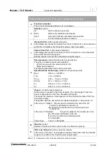
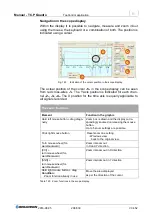
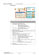
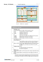
Channel group
– parameters
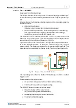
1
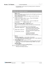
Channel X,
Text read-only indication of the channel name:
≙
Channel 1
– 4
2
Select signal,
button opens window
-3-
To define the related signal variables for the channel.
3
Select signal,
window
Selection of the required signals or signal variables
For further information see “Select signal” Fig. 128, page 213.
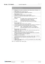
4
active,
check box
Selected:
The related channel is activated and records data.
A selection can be made in list box
-5-
.
Recorded data are shown on the display.
Cleared:
The channel and its data indication are disabled.
5
Scope value,
list box
The resolution for the ordinate (Y axis) is defined.
The unit is dependent on the signal selected. The resolution is normalised, i.e.
several channels can be shown at the same time on one X axis.
Value range:
0.001
– 100000 [unit]/div.; steps: 1, 2, 5 multiplied
by the related factor from 0.01 to 10000 in steps of ten
6
Scope value,
read-only indication
Indicates the actual channel value at time represented by the actual X axis
position of the cursor.
The unit indicated is dependent on the selected signal
-3-
.
Difference measurement indication if difference measurement is activated,
for further information see Fig. 125, page 209.
7
Address,
read-only indication
The address range in the memory in the TopCon power supply in which the
signal variable is saved. Indication of the address in hex code.
8
Signal name
Indication of the signal name, e.g. “siCTR_ActUmodule” for the output voltage
from a single device.
Table 123
Parameters for the “Channel” group.


