Manual - TC.P Quadro
TopControl application
2016-08-05
215/330
V04.52
6
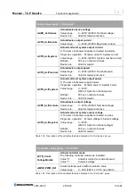
Actual values group
– “Act.values”
siADC_ActUsense
Actual device sense voltage
Value range:
0
– 4000; (4000
≙
Nominal voltage)
Device role:
Valid for master and slave
siCTR_ActImodule
Actual device output current
Value range:
0
– 4000; (4000
≙
Maximum current)
siCTR_ActIsystem
Actual multi-unit system output current
.
≙
The sum of all power supplies connected in parallel.
Single dev. operation: Module current
≙
System current
Value range:
0
– 4000; (4000
≙
System nominal current)
Refresh:
300
s x number of slaves
Device role:
Valid for master
siCTR_ActPmodule
Actual device output power
Value range:
0
– 4000; (4000
≙
Nominal power)
Device role:
Valid for master and slave
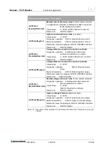
siCTR_ActPsystem
Actual multi-unit system output power
.
≙
The sum of all power supply powers.
Single dev. operation: Module power
≙
System power
Value range:
0
– 4000;
(4000
≙ System
nominal power)
Refresh:
300
s x number of slaves
Device role:
Valid for master
siCRT_ActUmodule
Actual device output voltage
Value range:
0
– 4000; (4000
≙
Nominal voltage)
Device role:
Valid for master and slave
siCTR_ActUsystem
Actual multi-unit system output voltage
.
≙
The sum of all power supplies connected in series.
Single dev. operation: Module voltage
≙
System voltage
Value range:
0
– 4000;
(4000
≙ System
nominal voltage)
Refresh:
300
s x number of slaves
Device role:
Valid for master
Table 125
Description of the variables that are allocated to the “Act.values” group.
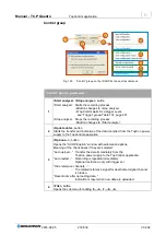
Controller values group
– “Controller”
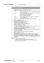
bCTR_Const
VoltageModule
Actual controller mode
The following controller modes are indicated:
Value “0”:
Constant current (or constant power)
Value “1”:
Constant voltage
uiMOD_PWM_Ref
Actual controller pulse width modulation value
Value range:
0
– 992; (992
≙ 100 % operation
)
Table 126 Description of the variables tha
t are allocated to the “Controller” group.

