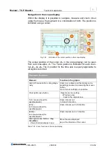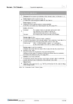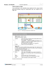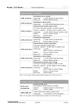
Manual - TC.P Quadro
TopControl application
2016-08-05
221/330
V04.52
6
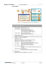
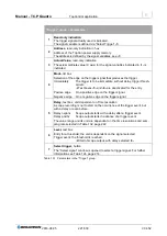
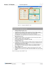
“Trigger” group – parameters
1
Read-only indication
The trigger signal actually used is indicated.
The signal variable is defined via “Select Trigger”
-7-
.
2
Address,
read-only indication in hex
Address of the TopCon power supply memory.
The address is defined by the signal variables, see
-7-
3
Actual Value,
read-only indication
The actual ordinate value (X axis) for the signal variables indicated in
-1-
is
indicated.
4
Mode,
list box
Selection of the edge on the trigger signal that produces the trigger.
Immediately
The trigger is to be immediate, without delay, trigger thresh-
old etc.
Text boxes
-5-
and
-6-
are deactivated for the entry.
Positive edge
On a positive edge on the trigger signal.
Negative edge
On a negative edge on the trigger signal.
5
Delay,
text box, unit dependent on Time resolution
A scope recording is not to start on the occurrence of the trigger event, but
with a delay or even before.
Delay negativ
Scope output starts with a delay after a trigger event.
Delay positiv
Scope output starts in advance of a trigger event.
The value range and its unit are dependent on the time resolutions and sam-
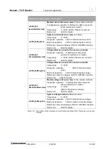
pling rate selected in Table 132, page 222.
6
Level,
text box
Entry for a threshold; the unit is dependent on the signal selected.
Trigger event: the threshold is reached.
Start of scope output, with delay selected
-5-
7
Select trigger,
button
The “Select signal” window is opened to select a trigger signal. For further
information see Table 124, page 214.
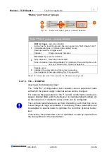
Table 131
Parameters in the “Trigger” group.


