Manual - TC.P Quadro
TopControl application
2016-08-05
226/330
V04.52
6
“Voltage sensing” group
Condition for the usage of the sense function:
TopCon power supplies not connected in series
Sense interface
Connection of the interface to the overall circuit
Effects of activation on other tabs:
<CONTROL> tab
<STATUS> tab
For further information on the hardware, sense activation and its effects
see chapter 3.2.4.4, page 55.
1
1
3 4
5
2
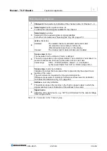
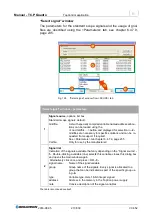
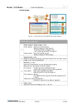
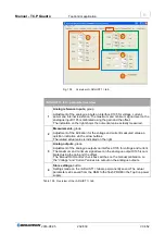
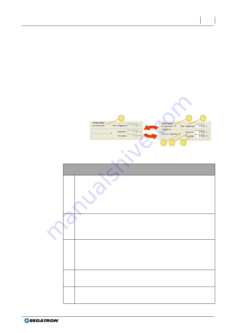
Fig. 134
“Voltage sensing” group – parameters.
“Voltage sensing” group – parameters
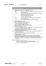
1
Use sense input, check box
Selected:
Function is switched on. All entries and check boxes for
“Voltage sensing” can be edited.
The following changes occur on the tabs:
<CONTROL> tab labelled with sense
<STATUS> tab - sense parameters available
Cleared:
Function is switched off
2
Max. voltage drop, text box
Maximum voltage compensation. The output voltage U
out
is as a maximum =
U
Set
+ Max.Voltage drop,
where the reference value U
Set
is defined via TopControl, analogue interface,
HMI/RCU or internally via the function generator.
3
Observe voltage drop, check box
Selected:
Monitoring of the voltage difference U
out
- U
sense
“Error level” /”Error delay” text boxes are activated.
Cleared:
Function is switched off
“Error level” /”Error delay” text boxes are deactivated
4
Error level, text box
If the threshold set for the voltage difference U
out
- U
sense.
is exceeded, the
device switches to the error status.
5
Error delay, text box
An “Error level” must be present for the time set before the device switches to
the error status.
Table 135
Parameters in the “Voltage sensing” group.

