Manual - TC.P Quadro
F) Miscellaneous
2016-08-05
306/330
V04.52
9
9.1.16.
F) Miscellaneous
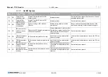
Flash
Code
Error
Error message
TopCon (Long)
Description
Possible Cause
Counteraction
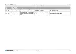
16-1
F0
Voltage sensing not
allowed in series
configuration
Enabling the sense functionality in
the series operation is not allowed.
Enabling the sense functionality in
the series operation is not al-
lowed.
Disable the sense functionality
16-2
F1
Wrong option code An invalid option code was set.
An invalid option code was set.
Reset the option code to all zero and restart the
device; installed software options will *not* be
removed by this. If necessary contact customer
support.
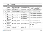
16-3
F2
Interlock open
Once the interlock circuit is opened,
the power stage switches off.
The dummy plugs of the interfaces
X105 and X101/X102 has not
been wired properly.
Use the correct plugs for interface X101, X102 and
X105.
16-3
F2
Interlock open
Once the interlock circuit is opened,
the power stage switches off.
The interlock circuit has not been
wired properly (check TopCon
manual for correct cabling).
Close the interlock circuit in a different way, e.g.
relais contact, external emergency OFF signal).
16-3
F2
Interlock open
Once the interlock circuit is opened,
the power stage switches off.
Interlock circuit was opened by an
external protection circuit.
Check the reason why the protection circuit was
activated.
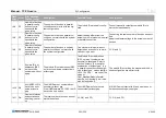
16-4
F3
External PWM
shut-down
Switching off of the power stage was
produced by an external signal.
This signal is not wired to the out-
put. Thus only a very strong EMI
interference is able to trigger this
error.
Find the EMI sources e.g. contactors without free
wheeling diodes.
16-5
F4
Safety relais open
The protection circuit relay is not
closed.
External emergency off circuit or
interlock cabling are interrupted.
Check the reason why the emergency off circuit or
interlock are interrupted.
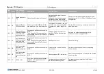
16-6
F5
Interlock=Lo mis-
sing
Attempt to switch VoltageON without
having set interlock signal to 0-level.
Attempt to switch VoltageON
without having set interlock signal
to 0-level.
Ensure that the interlock signal is down to 0 level
for at least 100ms prior to first voltageON signal.
(ISR surveillance).
16-7
F6
Interlock closed but
safety relay is open
(interlock must be
open too)
Clearing signal of Integrated Safety
Relais (ISR) is on 0-level (emergen-
cy stop), but the interlock signal is
not on 0-level
Clearing signal of Integrated Safe-
ty Relais (ISR) is on 0-level
(emergency stop), but the inter-
lock signal is not on 0-level
Ensure conjoint switching of ISR and Interlock
(within 100ms)


