Manual - TC.P Quadro
Technical data
2016-08-05
34/330
V04.52
3
3.1.1.4. Device rear side
2
1
5
6
2
3
5
6
3
7
1
1
4
4
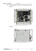
Fig. 11
Device rear side on the TopCon Quadro 10/16 kW and 20/32 kW.
Controls (cf. Fig. 11)
1
DC output
Plus and minus pole
2
Sense connection
For the selection of menu items and scaling of parameters
3
Regulated fans
As an option there may also be connections for the water cooling (LC) (option)
4
Mains connection
300-400/480VAC
5
Blind cover strip
Can be removed for further interfaces
6
Interfaces,
D-Sub
Upper area: CAN communication interfaces X101/X102
Lower area: analogue and digital interface X105
7
Auxiliary fuse
For the internal 24 V supply
Only for the device variant 10/16 kW
On the device variant 20/32 kW the fuse is inside the device
Table 14
Rear side of TopCon power supply 6 U and 9U.


