Manual - TC.P Quadro
Technical data
2016-08-05
41/330
V04.52
3
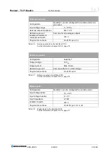
Digital outputs
Configuration
Quantity 3, can be configured to a certain extent
Relay contacts
Floating, 2x normally open, 1x change-over
Max. switching voltage
250 V
AC;
50 V
DC
Max. switching current
1 A
Isolation in relation to
controller and earth
125 V
Physical connections
On X105: pin 10, 11, 12, 13, 21, 22, 23
Table 29
Digital outputs on the interface X105.
Further information: chapter 3.3.3.6, page 77.
3.1.7.3. CAN communication interfaces X101/X102
Tasks
Communication between the devices in multi-unit operation
Safety circuit interlock
Terminating resistor
Pin definition
for the interface X101/X102: chapter 3.2.4.7, page 64
Interfaces X101 /X102 on the device rear side
1
X101
interface,
D-Sub, 9-pin
For connecting interlock or terminating resistor to the CAN bus
2
X102
interface,
D-Sub, 9-pin
For connecting interlock or terminating resistor to the CAN bus
Table 30
Short description of the interfaces X101/X102.
Further information: chapter 3.2.4.6, page 61.


