Manual - TC.P Quadro
Control
2016-08-05
71/330
V04.52
3
3.3.
Control
3.3.1.
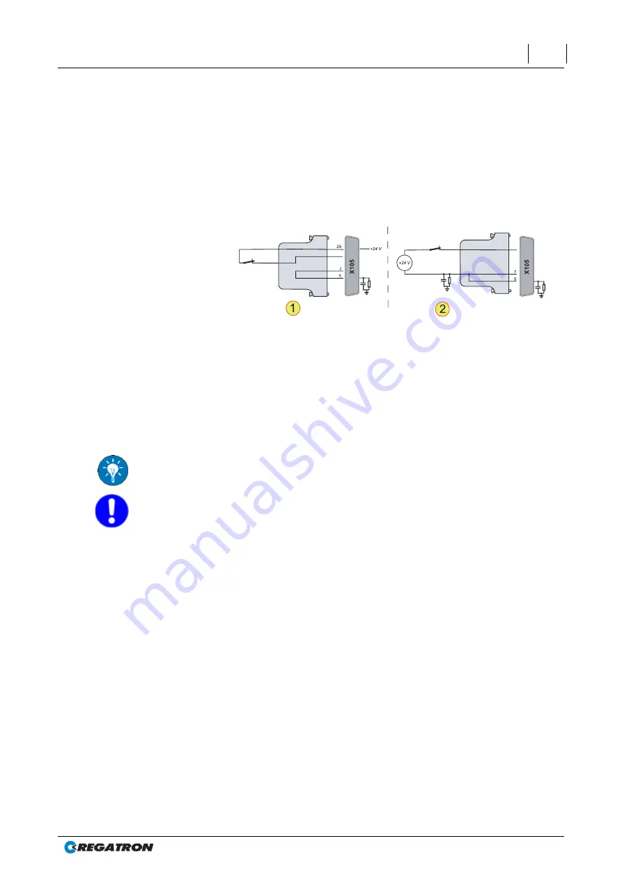
Interlock output inhibit
TopCon power supplies have a feature for rapidly inhibiting the output
using an interlock signal.
All external EMERGENCY STOP contacts must close the interlock cir-
cuit for operation to be possible.
24
24
In te rlo ck
In te rlo ck
C OM
0 VD C
C OM
0 VD C
+24VDC
Fig. 32
Example interlock circuit on the interface X105.
-1-
External EMERGENCY STOP button with internal voltage source.
-2-
External EMERGENCY STOP switch with external voltage source.
With interrupted interlock circuit
The power stage is switched off directly via a hardware link.
The controller remains switched on.
The device changes to the state: “Error”.
To work using the TopCon power supply (or a system with TopCon
modules), check that the interlock circuit is actually closed.
Ensure that the correct dummy plug has been used for the termination
of the interface X101.
For further information see chapter 3.2.4.6, page 62.
The description of the interlock circuit for multi-unit systems is different
due to the utilisation of the interface X102 for the different devices in the
system.
For further information see Fig. 70, page 135.


