background image

Manual –TC.GXS


2016-09-16 


10 / 43


Template V02.11


1.2.2. 

Reverse polarity protection (RPP) function by default  

Overview of voltages and current 

+

-

U

Sense Internal

U

Intern

U

Batt

U

Rail

I

Charge

RPP-Controller

DC relay

9

3

10

1

Device

U

Sense External

U

X104

14

+

-

13

Sense positive

R

Sense negative

R

PTC

PTC

X104

12

Sense RPP

U

Controller


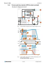
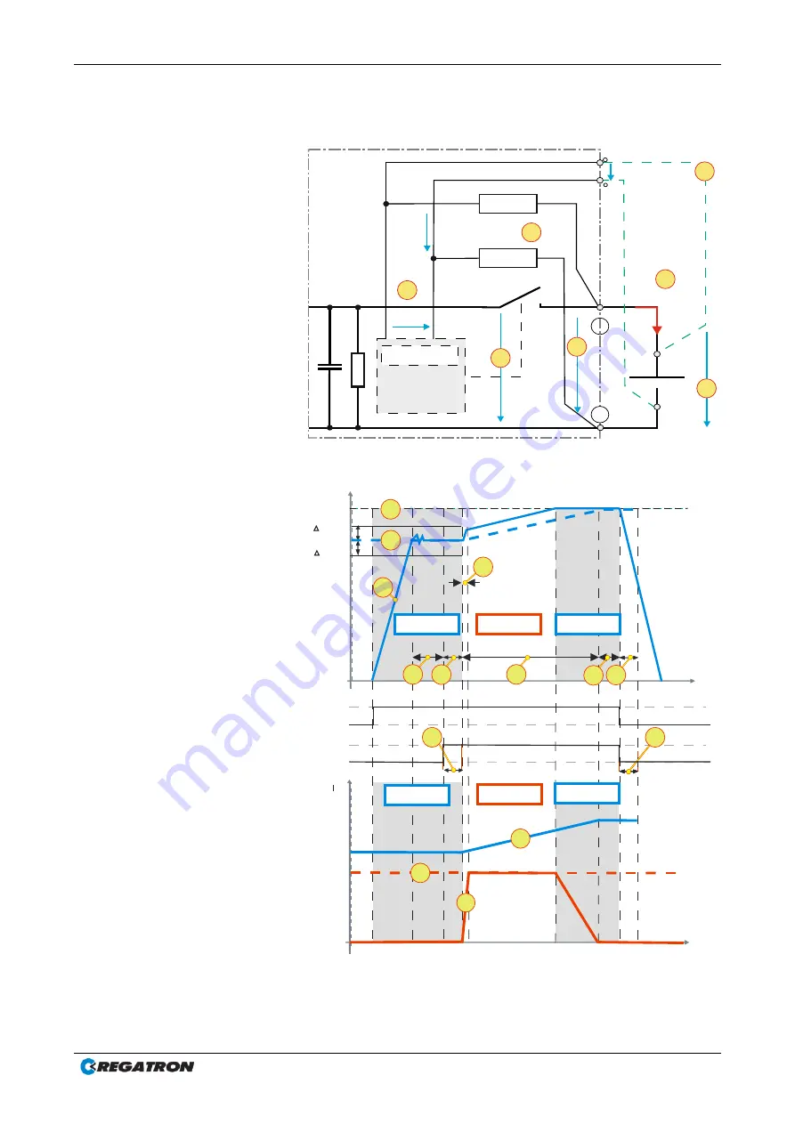
Fig. 2  Principle schematic diagram shows the charge voltage and current. 

Voltage

ON

Preset

OFF

Switch

U

=+1%

=-1%

Time

Voltage

Voltage

ON

Preset

OFF

Switch

close

U

Time t

U

U

U

Batt

0

current controlled

Output

Preset

I

Time t

0

current controlled

Voltage
Current

U

Rail

voltage controlled

voltage controlled

9

voltage controlled

voltage controlled

10

open

11

2
3

1

5

4 8

8

7

6

8

8


Fig. 3  Function of RPP at the example of a battery while switching on/ off 

and the charging procedure.  

The figure shows a simplified charging curve. 

Summary of Contents for TopCon TC.GXS

Page 1: ...Additional Information to the TopCon TC GXS device Programmable Regenerating DC Sink Version V01 15 Your distributor ...

Page 2: ...tion corresponds to the development situation at the time of going to print and is therefore not of a binding nature Regatron AG reserves the right to make changes at any time for the purpose of technical progress or product improvement without stating the reasons In general we refer to the applicable issue of our Terms of delivery Manufacturer Information on the manufacturer Regatron AG Tel 41 71...

Page 3: ...sonnel who are operating the device These operating instructions supplements to the actual TopCon TC GSS operating manual It is possible to download the newest TopCon TC GSS manual from the website www regatron com Mortal danger due to electric shock Due to the high operating voltage of the device and possible arcing in related applications there is a risk of injury Parts of the system may be dama...

Page 4: ...s injuries or fatality For a possibly hazardous situation that could result in damage to the product or another item in its surroundings Tab 3 Basic hazard and warning information Further warning and hazard information Pictogram Meaning DANGER WARNING or CAUTION due to electrical power DANGER WARNING or CAUTION related to suspended load Tab 4 Symbols included in the table can be used for more spec...

Page 5: ...th the device Tab 6 Additional information so that you can find possibly important information quickly Open questions In you have any questions your TopCon sales partner will be pleased to be of assistance However you can also reach Regatron support at the following address Customer support Regatron AG Tel 41 71 846 67 44 Kirchstrasse 11 Fax 41 71 846 67 77 9400 Rorschach www regatron com SWITZERL...

Page 6: ... 14 1 3 2 Control 14 2 GENERAL INFORMATION ON SAFETY AND HAZARDS 15 2 1 Categorisation of the hazard areas 15 2 2 Personnel area 16 2 3 Systems and material area 18 2 4 Mains connection area 20 2 5 Surrounding area 20 2 6 Transport area 21 2 7 Area related to interaction with the system 22 2 8 Ordinances and regulations 23 3 CONTROLS AND DISPLAYS 24 3 1 Elements of the TopCon TC GXS standard inter...

Page 7: ...ion 33 5 3 3 Optimisation of the control and monitoring functions 34 6 SYSTEM OPERATION 35 6 1 Important controls 35 6 1 1 EMERGENCY STOP 35 6 1 2 System main switch 36 6 2 Switching on and off the system 36 6 2 1 Prerequisites for successful switching on 36 6 2 2 Switching on the system 36 6 2 3 Switching off the system 36 6 2 4 Device self test 37 6 2 5 Function test 37 6 3 Specifying set values...

Page 8: ...power current or voltage several TopCon modules can be connected in series or in parallel Reverse polarity protection The devices are equipped with RPP by default Restriction on usage TopCon TC GXS power supply devices connected in series are not allowed to exceed a total DC voltage of 1500 VDC If you do not comply with this specification You will no longer be covered by the scope of the Low volta...

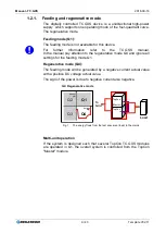
Page 9: ...generative mode Q4 and ignore all settings for the feeding mode Q1 Regenerative mode Q4 The feeding mode will be generated by a negative current actual value with a positive DC voltage actual value The sign of the power is due to negative current also negative TopCon TopCon Q4 Regenerative mode TopCon aaster TopCon Load Q4 Voltage U V Current I A Q1 Q2 Q3 To Grid Fig 1 The energy flows from the te...

Page 10: ...ller Fig 2 Principle schematic diagram shows the charge voltage and current Voltage ON Preset OFF Switch U 1 1 Time Voltage Voltage ON Preset OFF Switch close U Time t U U UBatt 0 current controlled Output Preset I Time t 0 current controlled Voltage Current U Rail voltage controlled voltage controlled 9 voltage controlled voltage controlled 10 open 11 2 3 1 5 4 8 8 7 6 8 8 Fig 3 Function of RPP a...

Page 11: ... nominal voltage Default value 100 ms 5 Ramp time The internal controller circuit tries to reach the preset voltage UPreset If the DC relay is closed immediately the controller works as a current controller The charge current ICharge produces a voltage ramp 6 Battery is charged The battery has reached the preset charging voltage UPreset while the TopCon device is running 7 Period of charging Time ...

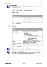
Page 12: ...ver the PTC resistors The resistors protect the sense lines Tab 9 Explanation of the figures Power on In case of UPreset UBatt At power on the DC relay switch is opened At first the TopCon device tunes in to battery voltage UBatt 3 to avoid high inrush currents The voltage value must be stable for 100 ms timer 4 Stable means that the voltage of the TopCon device 3 does not exceeded 1 of the batter...

Page 13: ...in additionally will not be activated not closed The voltage URail UBatt applies at the rail lines No current will flow into or from the battery Power off At power off the DC relay needs a short time 8 to open the connection because of its mechanical inertia Meanwhile the TopCon decreases its output voltage The voltage at the rail lines URail equates to the voltage UBatt 10 When the DC swich opens...

Page 14: ...terface Built in HMI Option in the TC GXS device Used for operation Start Stop Set value specification Function engine set value specification Selection of pre defined time dependent functions Selection of pre defined V I characteristics Setting of the most important parameters RS 232 Parameterisation via the PC software TopControl see also TopCon TC GSS manual Analogue digital interface X105 Usag...

Page 15: ...e Low voltage directive it is to be operated by adequately trained and instructed personnel 2 1 Categorisation of the hazard areas The assessment of the effects of hazards from low voltage systems with a flow of energy for supply and possibly regeneration is divided into the following areas TopCon power supply device Personnel area Mains connection Systems and material Surrounding area Interaction...

Page 16: ...orking it should be rigorously applied during all connection and wiring work Follow the rules 1 Electrically isolate 2 Secure against switching back on 3 Short circuit 4 Connect to earth 5 Report and instruct After shut down the short circuiting of the outputs and earthing are particularly important if reactive loads or loads that store energy accumulators capacitors ULTRACAP etc are used b Work i...

Page 17: ...ests insulation fires and short circuits may be caused At particular risk are connectors switchgear and cable terminals Check these parts particularly carefully and at regular intervals Use wiring material suitable and stipulated for your application with the related insulation class Monitor your system actively or passively using appropriate sensors or by monitoring parameters Arcing and sparking...

Page 18: ...itable fire fighting equipment CO2 fire extinguisher If possible use fire extinguishers with asphyxiation action to keep the secondary damage low Electromagnetic fields Like any electrical system TopCon low voltage systems produce electrical and magnetic fields However these fields comply fully with the usual standards Note however that particularly the EM fields from your wires and equipment conn...

Page 19: ...ing The monitoring of the maximum speed with intervention in the safety chain is recommended above all if the system runs unmonitored Handling stores containing large amounts of energy Modern energy storage systems are able to absorb very large amounts of energy This situation has the following consequences The cabling should not just comply with the maximum charging and discharging currents to be...

Page 20: ...es during the switch on process 2 5 Surrounding area TopCon power supply devices are generally forced air cooled Despite the very high efficiency a power loss occurs in the components that must be dissipated in the form of heat to the surroundings The energy is dissipated with the aid of forced ventilation to the rear of the TopCon device It is to be ensured that the rooms in which TopCon power su...

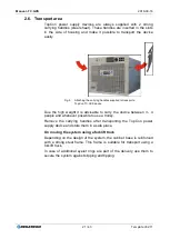
Page 21: ... device Due the high weight it is advisable to carry the device between 3 4 people and whenever possible to use a trolley Remove the carrying handles after transporting the TopCon power supply device and store them in a safe place On moving the system using a forklift truck Depending on the design of the system the cabinet base is reinforced with a strong steel frame This frame is suitable for tra...

Page 22: ...the system Compliance with the design data for the specific system is a prerequisite for malfunction free operation Load systems can have significant effects on the power source The following points are to be noted 1 The maximum voltage specified is not allowed to be exceeded 2 Protective measures must be provided against voltage spikes on the load side and their function must be monitored voltage...

Page 23: ...operating voltage internally up to 690V AC and the high output voltages up to 500V DC an industrial electrical power supply represents a mortal hazard To avoid serious injuries or significant damage only appropriately qualified personnel who are familiar with industrial electrical power supplies are allowed to work on the devices These individuals must carefully read these operating instructions p...

Page 24: ...ng the TopControl application Use the Interface RS 232 REAR or the Ethernet interface on the device back side to remote the device Pay attention that only one remote interface can be used to remote the device at the same time 3 DEVICE LED indicator Indication of the device status Green POWER Yellow STATUS WARNING Red ERROR 4 CONTROL LED indicator Green LED illuminates in front of the related label...

Page 25: ...ton Opens the main menu 6 ON OFF switch ON Green LED illuminated On reaching the operating state the output value set is present on the device output OFF Green LED is off device output is electrically isolated 7 REMOTE switch Change over as to whether the TC GSS power supply is to be remotely controlled Deactivated Red LED off HMI is ready for entries Activated Red LED illuminated HMI is remotely ...

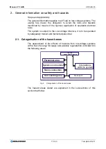
Page 26: ...al 4 2 System control internal The CAN bus interface X101 of master is terminated with the dummy plug X101 CAN TERM interlock The CAN bus interface X101 of the following slave device is connected to the interface X102 of the previous TopCon TC GXS master device via CAN CABLE The interface X102 of the last TopCon TC GXS slave device is terminated with a X101 CAN TERM For further information on the ...

Page 27: ...ug 1 Dummy plug 2 1 DC DC Dummy plug Fig 8 System in series operation master device 1 and slave device 2 Sources 1 2 Device addresses Master device and its address Master AH 0 AL 0 Slave devices and their addresses Slave AH 0 AL 1 CAN Bus CAN Cable connection X101 of Slave 1 is connected with X102 of Master Dummy plug 1 X101 is terminated with CAN TERM interlock X102 is terminated with CAN TERM So...

Page 28: ...ts address Master AH 0 AL 0 Slave devices and their addresses Slave AH 1 AL 0 CAN Bus CAN Cable connection X101 of Slave 1 is connected with X102 of Master Dummy plug 1 X101 is terminated with CAN TERM interlock X102 is terminated with CAN TERM Software configuration TopControl CONFIG tab Matrix multi unit system Number of Devices Inline 1 Number of parallel lines 2 Tab 15 System configruation 1 O...

Page 29: ...urrents using an adequate cable cross section Pay attention to the information at the position of the hazard Wait up to 15 minutes In the devices built in there can be dangerous voltages after switching off the mains voltage as well as in case of loads that store energy Only use the devices for the intended application and type of load In particular the mains voltage must match the information on ...

Page 30: ...fit new devices For further information on the transport area see section 2 6 Page 21 5 2 2 General information on installation Comparison of characteristic data in the documentation and on the product Do the type plates match the order and delivery documentation Are the device nominal data suitable for the intended application Do the cables etc supplied etc match the intended connections Further ...

Page 31: ...eens earthed at both ends Star topology earthing suitable for EMI of the device Screen connectors that are earthed directly via earthed sockets on the electrical power supply 5 2 4 System mains connection Possible injury and damage Injury due to missing or incorrect PE connection Avoidance On completion of connection work check the cables connected for firm fixing The mains connection is made On s...

Page 32: ...k check the cables connected DC DC DC DC 1 2 Fig 10 Connection of DC plus and DC minus in parallel 1 serial device mode 2 Load connection The load is connected to terminals DC positive and DC negative according Fig 10 Please note the following points For installation location refer to TC GSS manual The system must be electrically isolated on the system side and load side and secured against switch...

Page 33: ... Are the mains connections wired correctly Loads connected with correct polarity In case of using sense Is it connected correctly to load or DC bars of TC GXS device Control signals connected correctly External interlock EMERGENCY STOP circuit safety bus wired 5 3 2 Parameterisation The system and device parameterisation for the foreseen application is taken into account in the factory settings Th...

Page 34: ...e steps can be defined An external oscilloscope or the internal scope function can be used to measure the currents and voltages at the same time while the controller settings change with the aid of TopControl Operation with a square wave engine or the variation of the control parameters in the boundary area can result in oscillations and in some circumstances place the load connected at risk Durin...

Page 35: ...or the appropriate length of time before you touch the outputs If there is no load on the system output wait at least 1 min before you touch the outputs 6 1 1 EMERGENCY STOP In case that an EMERGENCY STOP is used Activating the EMERGENCY STOP Press the EMERGENCY STOP mushroom head button The EMERGENCY STOP mushroom head button latches The DC output is electrically isolated Resetting the EMERGENCY ...

Page 36: ...ronts of the related TopCon TC GXS devices System main switch is switched off switch position OFF The system is configured for multi unit operation For further information see TopCon TC GSS manual 6 2 2 Switching on the system Switch on the system main switch switch position ON TopCon TC GXS devices start the device self test On the HMI actuate the ON OFF pushbutton Pushbutton indicator LED illumi...

Page 37: ...minates or flashes In this case the state machine changes to the Error state Using the software application TopControl and a PC more detailed information on the causes of the error can be requested via the RS 232 interface and the necessary corrective actions can be taken For further information on errors see TopCon TC GSS manual 6 2 5 Function test With the mains voltage switched on the control s...

Page 38: ...ifferent interfaces Analogue interface X105 Integrated operating panel HMI Remote Control Unit RCU PC application TopControl via RS 422 rear RS 232 front The active interface is set via the HMI or in TopControl For further information on specifying set values with the different interfaces see TopConControl manual ...

Page 39: ...Miscellaneous 7 6 Communication 23 N IBC Inverter 2 8 7 Internal Modulator 24 P not used 9 8 Internal AD overrange 1 25 Q not used 10 9 Internal AD overrange 2 26 R not used 11 A Internal AD underrange 1 27 S not used 12 B Internal AD underrange 2 28 T not used 13 C Login 29 U not used 14 D Configuration 30 V not used 15 E Not def group 14 31 W Internal 2 16 F Miscellaneous 32 X Communication 2 Ta...

Page 40: ...le cause of the malfunction group error and detail error The following illustration shows a period in the indication cycle Fig 11 Sequence example for a flashing code Error codes and warning codes are identical All errors and warnings are output one after the other based on the scheme above Then the flashing sequence starts again with the first error or first warning Start 1 2 3 nG Pause 1 2 3 4 5...

Page 41: ...ges 4 Show Warndetail Same as in Show Errordetail only for warnings 3 Error history button List of the error messages that have occurred is opened 4 Error Warndetails 1 Window for indicating errors warnings An error indicated is listed in the related error group An error description has an error code and error keywords This information is used for troubleshooting using an error list 5 Show module ...

Page 42: ... via HMI RCU Press the ESC button on the active HMI panel The system is ready for operation again Press ON OFF on the active HMI panel Indicator LED illuminates green Power is output again on the output Acknowledging and starting operation using TopControl Press Clear error on the CONTROL tab The system is ready for operation again Press VOLTAGE ON on the CONTROL tab Power is output again on the o...

Page 43: ...Manual TC GXS 2016 09 16 43 43 Template V02 11 8 Maintenance For further information on maintenance work and the procedure of the support contact refer to the TC GSS manual ...

Reviews: