14
|
Regency U31-10 Gas Fireplace Insert
|
14
installation
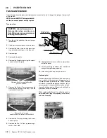
Diagram 1
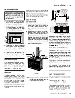
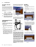
The smoke should be drawn into the spill tube. If
the smoke is still not drawn into the spill tube, turn
the unit off and check for the cause of the lack of
draft. If necessary, seek expert advice.
For wind turbulent sites, a wind cap may remedy
the problem.
Note: The thermally activated safety switch will
sense the change in temperature and shut down
the gas valve in the event of a severe downdraft
or a blocked or disconnected vent. The switch
acts as a safety shut-off to prevent a build-up
of carbon monoxide. If the flue is blocked or
has no "draw", the switch will automatically
shut off the supply of gas within 5 - 10 minutes.
Tampering with the switch can result in carbon
monoxide (CO) poisoning and possible death.
If the heater turns off because of lack of draft
during the spillage test, check for the cause and
if necessary, seek expert advice.
The thermally actuated safety switch will auto-
matically reset after it has cooled off. The switch
will continue to cycle until the draft problem is
corrected. DO NOT BYPASS OR DISCONNECT
THIS SWITCH.
OPTIONAL
BRICK PANEL
1.
Unwrap the brick pattern panels from the pro-
tective wrapping.
2.
Remove the safety screen and glass front if it
is already installed.
3.
Put the rear brick panel flat against the back of
the unit.
TEST FOR FLUE
SPILLAGE
A " spillage" test must be made before the
installed unit is left with the customer. Follow
the procedure below:
1.
Start all exhaust fans in the home and then
close all external doors and windows in the
house.
2.
Light the unit and set controls to maximum.
Turn fan off.
3.
After five minutes, test that there is a “pull” on
the flue by placing a smoke match, cigarette
or similar device which gives off smoke, in
front of the spill tube. To ensure a valid test,
place a scrap piece of sheet metal (or other
noncombustible material) between the spill
tube and the upper louver, this will prevent the
natural convection of the unit from interfering
with the test. See Diagram 1.
GAS INSERT AERATION
SYSTEM
The aeration adjustment rod is attached to the air
shutter which is located just above the orifice bracket.
The rod is used to adjust the aeration on the main
burner without having to take the appliance apart.
The burner aeration is factory set but may need
adjusting due to either the local gas supply, air
supply or altitude.
Natural Gas: 3/8" (9.5mm) open
Propane:
3/8" (9.5mm) open
Note: Any damage due to carboning resulting
from improperly setting the aeration
controls is NOT covered under warranty.
Note: Aeration Adjustment should only be
performed by an authorized FPI Installer
at the time of installation or service.
4.
Before installing the side brick panels, loosen
the screws for the brick tabs enough so that you
can slide the brick clips on to the screws easily
but that the tabs are secure. For the location
of the side brick tab screws see Diagram 2.
5)
Slide brick panel under brick clips, tighten screws
securing clips to complete installation.
Back Panel
Brick clip
Diagram 1
Diagram 2
Diagram 3
Check for proper draft by placing a match close to
the draft check opening. This should be checked
after the unit has been operating for 15 min.
Summary of Contents for Energy U31-LP10
Page 1: ......
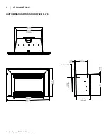
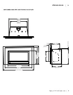
Page 5: ...4 Regency U31 10 Gas Fireplace Insert 4 dimensions UNIT DIMENSIONS WITH STANDARD FACE PLATE ...
Page 33: ...32 Regency U31 10 Gas Fireplace Insert 32 notes ...
Page 34: ...Regency U31 10 Gas Fireplace Insert 33 33 notes ...
Page 35: ...34 Regency U31 10 Gas Fireplace Insert 34 notes ...


