background image


Regency U31-10 Gas Fireplace Insert

  |     

27


|


27

maintenance

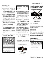
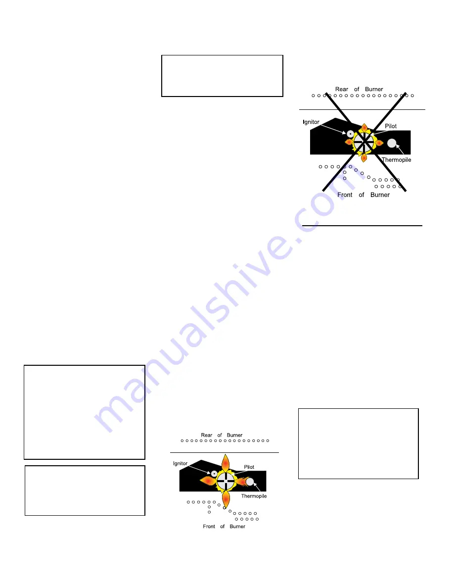
Top View of pilot flame

Correct flame pattern has four strong blue 
flames: 1 flowing around the thermopile and 
thermocouple and 1 reaching towards the 
rear burner and 1 toward the front(it does 
not have to be touching the burner).

Top View of pilot flame

Incorrect flame pattern will have small, prob-
ably yellow flames, not coming into proper 
contact with the rear burner or thermopile.

CAUTION:  ANY SAFETY SCREEN 

OR GUARD REMOVED FOR SER-

VICING AN APPLIANCE MUST BE 

REPLACED PRIOR TO OPERAT-

ING THE APPLIANCE.

WARNING:  DO NOT OPERATE 

APPLIANCE WITH THE GLASS 

FRONT  REMOVED,  CRACKED 

OR BROKEN. REPLACEMENT OF 

THE  GLASS SHOULD BE DONE BY  

A LICENSED OR QUALIFIED  

SERVICE PERSON.

MAINTENANCE 

INSTRUCTIONS

1)

  Always turn the gas valve to off before cleaning. 

For relighting, refer to lighting instructions. Keep 
the burner and control compartment clean by 
brushing and vacuuming at least once a year.


When cleaning the logs, use a clean soft paint 
brush as the logs are fragile and easily dam-
aged.

2)

  Clean (never when unit is hot) appliance, door 

and louvers with a damp cloth.  Never use an 
abrasive cleaner. The gold louvers (and optional 
gold door) may be scratched if abrasives are 
used to clean them.


The heater is finished in a heat resistant paint 
and should only be refinished with heat resistant 
paint (not with wall paint). FPI uses StoveBrite 
Paint - Metallic Black #6309.

3)

  Make a  periodic check of burner for proper posi-

tion and condition. Visually check the flame of 
the burner periodically, making sure the flames 
are steady; not lifting or floating. If there is a 
problem, call a qualified service person. 

4)

  The  appliance  and  venting  system  must  be 

inspected  before  use,  and  at  least  annually, 
by a qualified field service person, to ensure 
that the flow of combustion and ventilation air 
is not obstructed. 


During  the  annual  service  call,  the  burners 
should be removed from the burner tray and 
cleaned. Replace the embers but do not block 
the pilot.

5)

  Keep  the  area  near  the  appliance  clear  and 

free from combustible materials, gasoline and 
other flammable vapours and liquids.

6) 

Each time the appliance is lit, it may cause 
condensation and fog the glass.  This con-
densation and fog is normal and will disap-
pear in a few minutes as the glass heats up.


Never operate the appliance without the 
glass properly secured in place, with 
broken glass or with the door open.

7)

  Verify proper operation after servicing.

8) 

  Periodically  check  the  pilot  flames,  there 

should be three strong blue flames approx. 
3/4" long - 1 flame to the front burner, and 
1 to the thermopile and one to the left. See 
diagrams below.


If you have an incorrect flame pattern, contact 
your FPI dealer for further instructions.

CLOTHING OR OTHER FLAM-

MABLE MATERIAL SHOULD NOT 

BE PLACED ON OR NEAR THE 

APPLIANCE.

 
If the glass gasket requires replacement use 
7/8" flat glass gasket (Part # 936-243) for the Bay 
Front and for the Flush Front.

DOOR GLASS 

REPLACEMENT

Your  Regency  insert  is  supplied  with  high  tem-
perature, 5 mm Neoceram ceramic glass that will 
withstand the highest heat that your unit will produce.  
In the event that you break your glass by impact, 
purchase your replacement from an authorized FPI 
dealer only, and follow our step-by-step instructions 
for replacement.

Flush Glass Replacement

Slide old glass out of the side frames and replace 
with new glass. 

WARNING:  CHILDREN AND 

ADULTS SHOULD BE ALERTED 

TO THE HAZARDS OF HIGH 

SURFACE TEMPERATURE AND 

SHOULD STAY AWAY TO AVOID 

BURNS OR CLOTHING IGNITION.  

YOUNG CHILDREN SHOULD BE 

CAREFULLY SUPERVISED WHEN 

THEY ARE IN THE SAME ROOM 

AS THE APPLIANCE.

LOG REPLACEMENT

The unit should never be used with broken logs. 
Turn off the gas valve and allow the unit to cool 
before opening door to carefully remove the logs. 
The pilot light generates enough heat to burn 
someone. If for any reason a log should need 
replacement, you must use the proper replace-
ment log. The position of these logs must be as 
shown in the diagram under Log Installation.  

NOTE:    Improper  positioning  of  logs  may 

create carbon build-up and will alter 

the unit’s performance which is not 

covered under warranty.

GLASS GASKET

Summary of Contents for Energy U31-LP10

Page 1: ......

Page 2: ...mmable vapors and liquids in the vicinity of this or any other appliance WHAT TO DO IF YOU SMELL GAS Do not try to light any appliance Do not touch any electrical switch do not use any phone in your building Leave the building immediately Immediately call your gas supplier from a neighbour s phone Follow the gas supplier s instructions If you cannot reach your gas supplier call the fire department...

Page 3: ...armth and charm of a fireplace at the flick of a switch The models U31 NG10 and U31 LP10 of this series have been approved by Warnock Hersey Intertek for both safety and efficiency As it also bears our own mark it promises to provide you with economy comfort and security for many trouble free years to follow Please take a moment now to acquaint yourself with these instructions and the many feature...

Page 4: ...ion 13 High elevation 13 Draft hood connection 13 Venting 13 Gas pressure test 13 Gas insert aeration system 14 Test for flue spillage 14 Optional brick panel 14 Log set installation 15 Wiring diagram 18 Standard faceplate hearth trim install 19 Flush louver installation 20 Low profile faceplate installation 21 Safety screen installation removal 23 Optional wall thermostat 24 Final check 24 Operat...

Page 5: ...4 Regency U31 10 Gas Fireplace Insert 4 dimensions UNIT DIMENSIONS WITH STANDARD FACE PLATE ...

Page 6: ...Regency U31 10 Gas Fireplace Insert 5 5 dimensions UNIT DIMENSIONS WITH LOW PROFILE FACE PLATE ...

Page 7: ...ssachusetts requires the installation of a carbon monoxide alarm in accordance with NFPA 720 and a CO alarm with battery back up in the same room where the gas appliance is installed This is a copy of the labels that accompany each U31 10 Gas Insert We have printed a copy of the contents here for your review The safety label is located on a plate inside the base of the unit visible when the bottom...

Page 8: ...tly in line with the exhaust vent terminal for the horizontally vented gas fueled heating appliance or equipment The sign shall read in print size no less than one half 1 2 inch in size GAS VENT DIRECTLY BELOW KEEP CLEAR OF ALL OBSTRUCTIONS 4 INSPECTION The state or local gas inspector of the side wall horizontally vented gas fueled equipment shall not approve the installation unless upon inspecti...

Page 9: ...SHOULD BE CARE FULLY SUPERVISED WHENTHEY ARE IN THE SAME AREA AS THE APPLI ANCE TODDLERS YOUNG CHILDREN AND OTHERS MAY BE SUSCEPTIBLE TO ACCIDENTAL CONTACT BURNS A PHYSICALBARRIERSISRECOMMEND ED IFTHERE ARE AT RISK INDIVIDUAL INTHE HOUSE TO RESTRICT ACCESS TO A FIREPLACE OR STOVE INSTALL AN ADJUSTABLE SAFETY GATE TO KEEP TODDLERS YOUNG CHILDREN ANDOTHERATRISKINDIVIDUALSOUT OF THE ROOM AND AWAY FRO...

Page 10: ... fireplace chimney must be cleanandingoodworkingorderandconstructed of non combustible materials 6 The chimney cleanouts must fit properly 7 Refractory firebricks glassdoors screenrails screen mesh and log grates can be removed from the fireplace before installing the gas fireplace insert 8 Smoke shelves shields and baffles may be removed if attached by mechanical fasteners If any part is removed ...

Page 11: ... is firing correctly This includes a Clocking the appliance to ensure the correct firing rate b Adjusting the primary air if required to ensure that the flame does not carbon c Ensuring that the appliance is venting correctly MATERIALS REQUIRED No electrical power supply is required for the gas control to operate A 120 Volt AC power cord is hooked up to the fan Plug the 3 wire cord into a suitable...

Page 12: ...s Fireplace Insert 11 11 installation COMBUSTIBLE MANTEL CLEARANCES IN MASONRY INSTALLATION Clearances for Low Profile Faceplate with Safety Screen Clearances for Standard Faceplate Contour Faceplate with Safety Screen ...

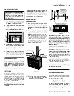
Page 13: ...the pilot cap to expose the pilot orifice 18 Unscrew the pilot orifice with the allen key and replace with the LP pilot orifice in the kit 19 Replace Burner Tray and reverse steps 5 to 1 20 Adjust the burner aeration setting to 3 8 to 3 8 as required for the best flame picture Fig 1 9 R e m o v e t h e b l a c k protection cap by hand fromthehi lowknob Fig 1 Fig 2 12 Flip the screw Fig 3 Fig 4 Fig...

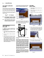
Page 14: ...gh the front of the unit therefore the front of the unit must be kept clear of any obstructions GAS PRESSURE TEST Theunitispresettogivethecorrectgasinputatthe specified manifold pressures shown on the label The maximum gas manifold pressure is Natural Gas 3 5 w c Propane 10 w c The manifold pressure is controlled by a regulator built into the gas control and should be checked at the pressure test ...

Page 15: ...he home and then close all external doors and windows in the house 2 Light the unit and set controls to maximum Turn fan off 3 After five minutes test that there is a pull on the flue by placing a smoke match cigarette or similar device which gives off smoke in front of the spill tube To ensure a valid test place a scrap piece of sheet metal or other noncombustible material between the spill tube ...

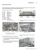
Page 16: ...2 154 Embers i 902 153 Rockwool j 902 179 P Vermiculite k 946 669 Platinum Embers supplied with packaged manual Note Install Optional Brick Panels prior to installing logs 1 Carefully remove the logs from the box and unwrap them The logs are fragile handle with care do not force into position 2 Sprinkle the vermiculite around the firebox base Take some of the embers approx 1 3 of the bag and sprin...

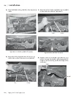
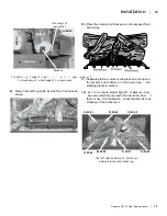
Page 17: ...Center Log E 02 47 over Log B 02 45 and across the cutout on Log A 02 43 Cutout Pin Cutout Notch 8 Position notch in Front Right Log F 02 48 on Log E 02 47 and push the bottom right edge against the bracket on the burner tray and the front edge of the rear burner Notch Bracket D 02 46 E 02 47 F 02 48 C 02 56 A 02 43 B 02 45 A 02 43 B 02 45 E 0 2 4 7 Logs A 02 43 C 02 56 and B 02 45 in position C 0...

Page 18: ...u t t nug aga n t t e bracket and t e front edge of t e rear burner Side View Page 3 of 3 11 Separate platinum embers and place on and around the embers and rockwool on the burner tray oid stacking platinum embers 12 est re to ensure proper light off makesure ame ows smoothly from one end of burner to the other f there is any ame hesitation check that area for any blockage of the burner port The 0...

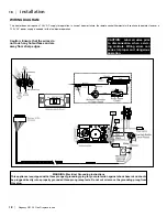
Page 19: ... Label all wires prior to disconnection when servic ing controls Wiring errors can cause improper and dangerous operation WARNING Electrical Grounding Instructions This appliance is equipped with a three pronged grounding plug for your protection against shock hazard and should be plugged directly into a properly grounded three prong receptacle Do not cut or remove the grounding prong from this pl...

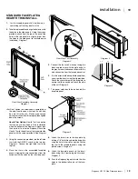
Page 20: ...aceplate side panels with the screws provided See Diagram 1 3 Using the connectors provided join the left side trim with the ON OFF switch to the top trim Diagram 2 Connect the right side trim to the top trim 4 Place the trim on the assembled faceplate panels aligning the wire connections from the switches with the notch on the left side panel 5 Connect the fan switch wires by taking the black and...

Page 21: ...tom Louver near the hinge Flip hinge over the Bottom Louver and secure using 3 screws FLUSH GLASS INSTALLATION 1 Install upper and lower trim 2 Slide the glass into the bottom glass support and secure with the glass clips using the 2 phillips head screws at the top Note To re install the glass reverse the procedure WARNING The use of substitute glass will void all product warranties Do not operate...

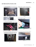
Page 22: ...am 5 Diagram 6 3 Tuck the wires into the clip to keep them away from the insert using the clip provided Attach the clip to the rear of the faceplate to en sure that the wires do not touch the side of the unit The power cord should be run behind the inner faceplate panel 4 Install the on off switch fan speed control box to the left hand bottom leg of the inner faceplate Controls located on the left...

Page 23: ...anel pins 11 Install safety screen see next page 9 Hook door frame on 2 pins over glass door in locations shown below in Diagram 10 7 Attach 2 brackets near the bottom of the unit with one screw as shown below in Diagram 8 left and right brackets are inter changeable 8 Attach Regency logo to bottom louver Install bottom louver by hanging louver on brackets installed in step 8 Final Install Diagram...

Page 24: ...on the safety screen into the slots on the unit 3 To remove lift screen assembly up and pull away from unit Note If the top and bottom glass trim supplied with the optional flush louvers is installed discard and recycle the glass trim as this not required when using the safety screen This is only used on previous models of fireplaces which do not use this optional safety screen ...

Page 25: ... on label at 15 minutes 2 If required adjusting the primary air to ensure that the flame does not carbon First allow the unit to burn for 15 min to stabilize CAUTION Any alteration to the product that causes soot ing or carboning that results in damage to the exterior facia is not the responsibility of the manufacturer Thermostat Wire Table Recommended Maximum Lead Length Two Wire When Using Wall ...

Page 26: ...tacts closing and is normal Pilot Flame While the pilot flame is on it can make a very slight whisper sound Gas Control Valve As the gas control valve turns ON and OFF a dull clicking sound may be audible this is normal operation of a gas regulator or valve Unit Body Firebox Different types and thicknesses of steel will expand and contract at different rates resulting in some cracking and ticking ...

Page 27: ...ment de modification de service ou d entretien peut provoquer des blessures ou des dommages matéri els Reportez vous au manuel du propriétaire de l information fournie avec cet appareil Pour obtenir de l aide ou des informations supplé mentaires consulter un installateur qualifié une agence de service ou fournisseur de gaz Important If the pilot does not hold turn pilot knob to OFF position Wait 5...

Page 28: ...ck the pilot 5 Keep the area near the appliance clear and free from combustible materials gasoline and other flammable vapours and liquids 6 Each time the appliance is lit it may cause condensation and fog the glass This con densation and fog is normal and will disap pear in a few minutes as the glass heats up Never operate the appliance without the glass properly secured in place with broken glas...

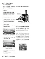
Page 29: ...bit of dish soap on the grommet so it will slide more easily onto the pin Check to make sure the fan is seated properly on the pins this is very important try to move the fan back and forth there should be no noise if there is check that the grommets haven t come loose When replacing the Burner Tray slide the aeration adjustment rod through the opening in the front of the Valve Assembly 1 Turn the...

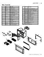
Page 30: ...ket 59 936 233 3 4 Rope Gasket 404 969 Conversion to LP Kit 919 435 Manual Not available as a replacement part Part Description 1 400 011 Fan Opening Cover 2 911 071 P Fan Motor 120 V 5 910 750 Power Cord 120 V 910 752 Wire Harness intermediate 6 Thermodisc cover 7 Thermodisc bracket 8 910 142 Thermodisc Fan Auto ON OFF 10 Drafthood Assembly 11 Spill Switch Bracket 12 910 220 Spill Switch 13 Level...

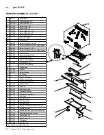
Page 31: ...urner Assembly NG LP 63 910 048 Pilot Assembly NG 4 flame convertible top 910 049 Pilot Assemby LP 4 flame convertible top 67 Firebox Base 69 402 935 Log Set 402 572 Ember Package 70 Air Channel 72 Glass Trim Retainer 73 Firebox back and top 74 Glass Gasket Retainer 75 404 050 Firebox Baffle 76 400 090 Brick Clip 77 404 005 Fan Access Plate 78 400 023 Thermodisc Bracket 79 400 068 Thermodisc cover...

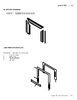
Page 32: ...05 900 Description Standard Faceplate Assembly Part 405 919 Description Oversize Faceplate Assembly 1 2 4 3 5 LOW PROFILE FACEPLATE Part 403 954 Description Low Profile Faceplate 1 Back plate Assembly 2 Bottom Louver 3 Right mounting bracket 4 Left mounting bracket 5 Front Frame ...

Page 33: ...32 Regency U31 10 Gas Fireplace Insert 32 notes ...

Page 34: ...Regency U31 10 Gas Fireplace Insert 33 33 notes ...

Page 35: ...34 Regency U31 10 Gas Fireplace Insert 34 notes ...

Page 36: ...ent parts and issue credit once the replaced component has been returned to Regency and evalu ated for manufacturer defect The authorized selling dealer is responsible for all in field service work carried out on your Regency product Regency will not be liable for results or costs of workmanship from unauthorized service persons or dealers At all times Regency reserves the right to inspect product...

Page 37: ...___________________________________________________ Phone ____________________________________________________________ Date Installed _______________________________________________________ Serial No ___________________________________________________________ Register your Regency warranty online www regency fire com Reasons to register your product online today View and modify a list of all your ...

Reviews: