Regency Plateau
®
PTO30-11 Outdoor Gas Fireplace
e |
13
13
|
installation
1
OUTDOOR SERIES
919-774a
01.25.21
OPTIONAL HARD WIRE KIT INSTALLATION
WARNING!
•
USE ONLY A GROUND FAULT INTERRUPTER (GFI) PROTECTED CIRCUIT WITH THIS OUTDOOR GAS APPLIANCE .
•
ENSURE THAT ALL POWER SOURCES HAVE BEEN SHUT OFF PRIOR TO BEGINNING ANY ELECTRICAL WORK.
•
DO NOT USE THIS APPLIANCE IF ANY PART HAS BEEN UNDER WATER.
•
CALL A QUALIFIED SERVICE TECHNICIAN IMMEDIATELY TO HAVE THE APPLIANCE INSPECTED FOR DAMAGE TO THE ELEC-
TRICAL CIRCUIT.
•
RISK OF ELECTRICAL SHOCK OR EXPLOSION. DO NOT WIRE 110V TO THE VALVE OR TO THE APPLIANCE WALL SWITCH.
•
INCORRECT WIRING WILL DAMAGE CONTROLS AND IS NOT COVERED BY THE WARRANTY.
•
ALL WIRING SHOULD BE DONE BY A QUALIFIED ELECTRICIAN AND SHALL BE IN COMPLIANCE WITH LOCAL CODES. IN
THE ABSENCE OF LOCAL CODES, USE THE CURRENT CSA22.1 CANADIAN ELECTRIC CODE IN CANADA OR THE CURRENT
NATIONAL ELECTRIC CODE ANSI / NFPA NO. 70 IN THE UNITED STATES.
A hard wire kit is available for this unit as an option, to hard wire this appliance, a qualified electrician must remove the cord connection, and wire
the appliance directly to the household wiring.
This appliance must be electrically connected and grounded in accordance with local codes, if hard wired.
In the absence of local codes, use the current CSA C22.1 CANADIAN ELECTRICAL CODE in Canada or the current ANSI/NFPA 70 NATIONAL
ELECTRICAL CODE in the United States.
SHUT OFF GAS AND ELECTRICAL SUPPLY BEFORE
STARTING THIS INSTALLATION.
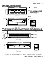
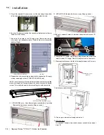
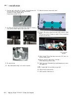
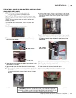
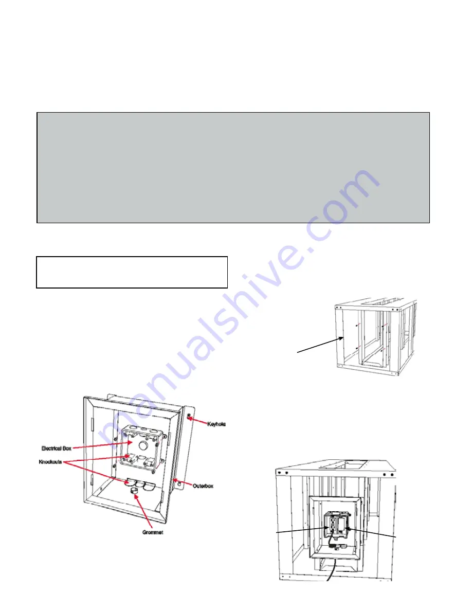
1. Install electrical box into the outer box with 4 screws (Diagram 1).
2. Depending on which side (or conduit size) the electrical outlet will be
installed, remove the corresponding knockouts in the outer box and
electrical box to allow access for the conduit wiring (supplied by others)
(Diagram 1).
ALL WIRING SHOULD BE DONE BY A QUALIFIED ELECTRICIAN
In the diagram below the outer box is installed. To install the outer box,
line up the keyholes on the box with corresponding screws (installed in
previous step) on the framing kit. When the box is in position, tighten the
screws. (PTO30/PTO50 only).
4. Run the conduit to the electrical box through the knockout and
complete the wiring of the electrical to the GFI circuit supplied with
the kit. Once electrical wiring is complete,Secure both the GFI circuit
and white blanking plate to the electrical box using 2 screws each.
Install electrical box into the outer box with 4 screws.
Note
(PTO30/PTO50 only)
:
If 2 burners are used, an additional AC adapter will be required to power the second burner.
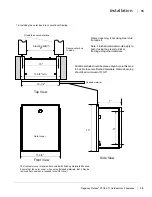
3. Install 4 screws into existing holes in the interior if using the optional
framing kit in locations shown in the diagram below. Keep screws
loose--do not tighten.
NOTE: If the optional framing is not used the outer box can be installed
into conventional framing. See Step 14.
4 screws into
framing
GFI Circuit
Blanking
Plate
Diagram 1
Important :This electrical box must be located within 10 feet of the burner(s) as the AC adaptor is 10 feet long and will not
reach the DC supply wire connection if any farther.
The 4 AA batteries do not need to be installed if using the AC
adaptor. The batteries would only be required in the event that
120V power is lost.
(PTO30/PTO50 only)
OPTIONAL HARD WIRE KIT INSTALLATION
Summary of Contents for Plateau PTO30
Page 45: ...Regency Plateau PTO30 11 Outdoor Gas Fireplacee 45 45 notes ...
Page 50: ......
Page 51: ......


