Regency U28-2/U43-3 ULTIMATE Freestanding Gas Heater
9
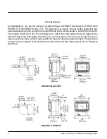
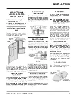
Side View
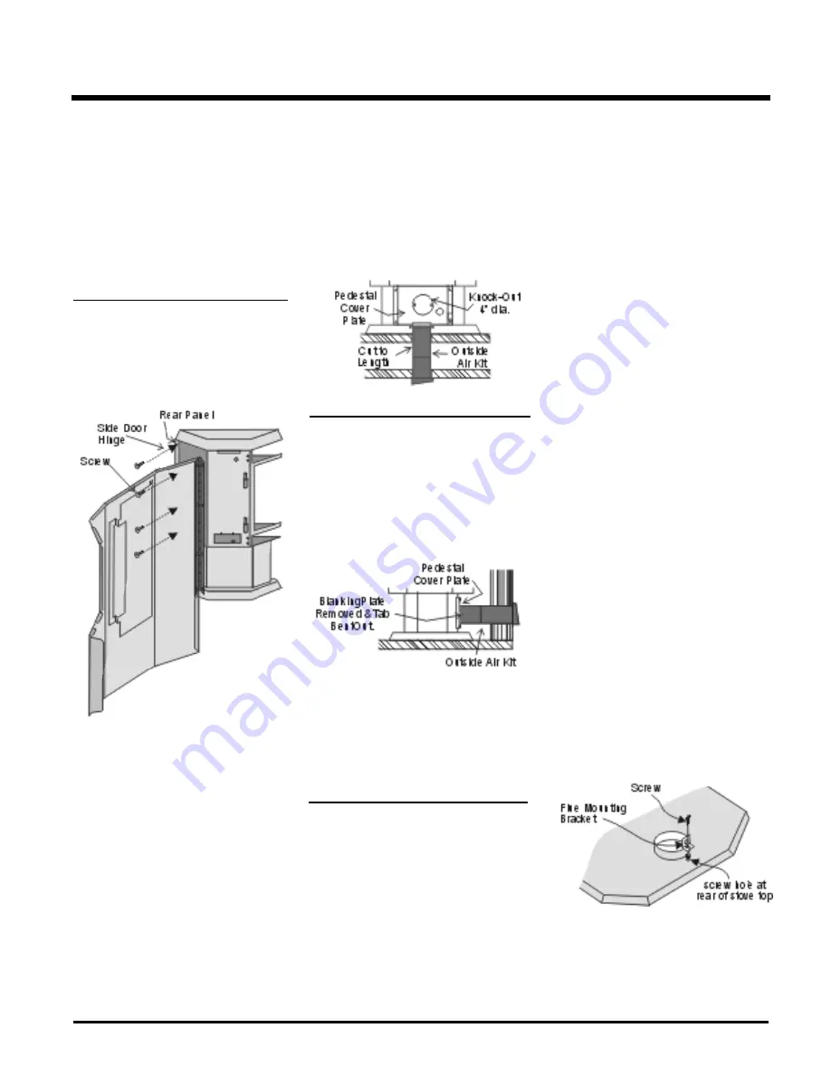
1) Remove the screws holding the 2 short
side doors to the unit.
2) Attach the long side doors to the stove body
using the screws provided (4 per door).
OPTIONAL OUTSIDE
AIR
Outside air for combustion can be brought in
either through the bottom of the pedestal or
through the rear plate of the pedestal.
Rear View
DRAFT HOOD
This heater has a draft hood built in. It must
not be altered, obstructed, or blocked in any
way, and the unit must be installed so that the
draft hood is in the same atmospheric pressure
zone as the combustion air inlet to the burner.
This heater must be properly connected to a
venting system. This heater is equipped with a
vent safety shutoff system.
For both bottom and rear "outside air" the Ped
-
estal Cover Plate must be installed. Loosen the
4 screws on the rear of the pedestal and slide
the cover plate over them. Slide the plate to the
left to center it and tighten down the 4 screws.
Outside Air Through
Pedestal Bottom
Once you have properly marked the position of
your unit as outlined in "General Information"
and "Clearances to Combustibles", cut a prop
-
erly sized hole though the floor directly under
your pedestal base to the outside. Pipe fresh
air into the pedestal area by using appropriate
metallic duct pipe with a mesh grill at the outside
termination. Do not remove the knockout.
WARNING: Operation of this heater when
not connected to a properly installed and
maintained venting system or tampering
with the vent safety shut-off system can
result in carbon monoxide (CO) poisoning
and possible death
.
HIGH ELEVATION
The U43 is approved in Canada for altitude
2000 ft. to 4500 ft. (CAN/CGA-2.17-M91) with
the orifice kit (Part # 591-975). For Natural
Gas installations above 4500 ft. follow current
CAN/CGA-B149.1.
In U.S.A., for installations above 2000 ft. refer
to current ANSI Z223.1 Sc8-8.1.2a appendix F,
for resizing orifice.
U28: OPTIONAL
LONG SIDE DOOR
INSTALLATION
INSTALLATION
VENTING
This heater is a vented appliance and must be
connected to a chimney/flue in accordance with
the installation codes.
Note: The rear pedestal cover plate is
only required when outside air is
being used. If using room air for
combustion, remove this plate from
the back of the pedestal.
For your safety this heater is equipped with a
vent safety switch designed to sense incorrect
venting and react by shutting down the gas
supply. This thermally actuated switch is located
within the draft hood and will detect either a
blocked chimney or backdraft condition where
the chimney flow has reversed. If this switch
shuts the unit down, it indicates a drafting
problem that must be identified and rectified
without delay - the thermally activated switch
must
never
be bypassed or disconnected as
a hazardous or deadly condition can result.
Venting Requirements
A four inch diameter vent is required. B-Vent,
Class A or Masonry with an approved liner
are all acceptable. For cosmetic or aesthetic
purposes 6" outer vent can be used as long as
an approved inner vent is installed. Fasten but
do not penetrate the inner sleeve of the B-Vent
when tightening the screw.
Follow all venting manufacturer’s requirements
and local building codes. In cold climates,
we recommend the use of insulated B-vent,
chase, and liners. For altitudes above 2000
ft. we recommend that a minimum flue height
of 12 ft. is used.
Flue Mounting Bracket
Attach the flue mounting bracket with the en
-
closed screw as shown in the diagram.
Outside Air Through
Rear of Pedestal
Remove the blanking plate from the rear of the
pedestal cover plate and bend the two tabs out
90 degrees. Pipe fresh air into the pedestal
area by using duct pipe with a mesh grill at
the outside termination. Attach the pipe to the
tabs with screws.


