18 |
Regency CI1203 / CI1253 Wood Cast Insert
18 |
installation
918-930
06/29/10
1
CI1200 | CI1250
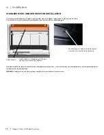
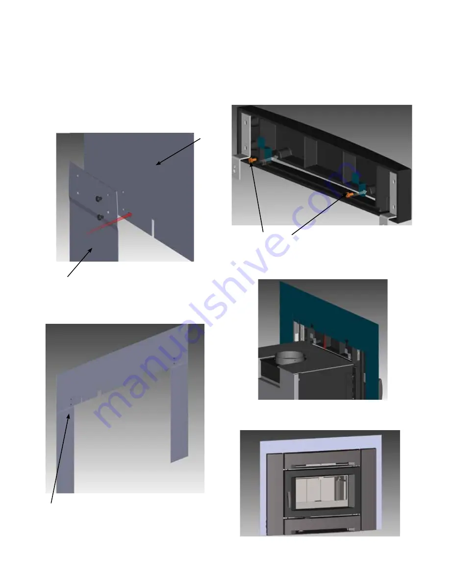
3 PIECE BACKING PLATE INSTALLATION
An optional backing plate is available in either a standard or custom
size.
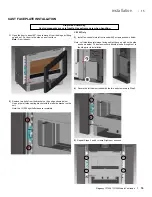
1)
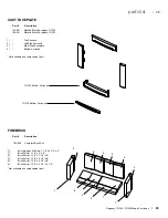
The backing plate is packaged in three pieces and requires assem-
bly. The legs of the backing plate are attached to the top plate with
2 screws on each side. See diagram 1 below.
Diagram 1
Leg
Top plate
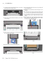
Diagram 2
Flush front face of
backing plate
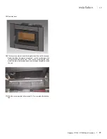
Diagram 3
Hex bolts
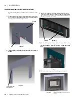
Diagram 4
Diagram 5
Standard backing plate shown on the
CI1250
2)
The pointed end of the screws should be facing the front of the back-
ing plate.
3)
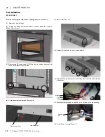
Install 2 clips to the back of the top cast faceplate with hex bolts.
If the unit is already installed - remove the top cast faceplate from
the unit if access is too diffi cult - see 'Cast Faceplate Installation' in
the owners manual for instructions.
4)
Slide the backing plate over the clips on the back of the cast top.
There are notches in the backing plate where it sits on the clips. If
the stove is installed - slide it out at least 6" to install the backing
plate.
5)
Slide stove back into position after backing plate is installed.
3 PIECE BACKING PLATE INSTALLATION


