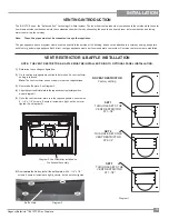
Regency Bellavista™ B41XTCE Gas Fireplace
23
INSTALLATION
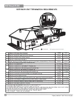
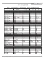
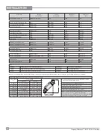
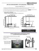
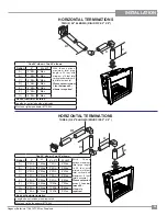
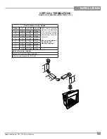
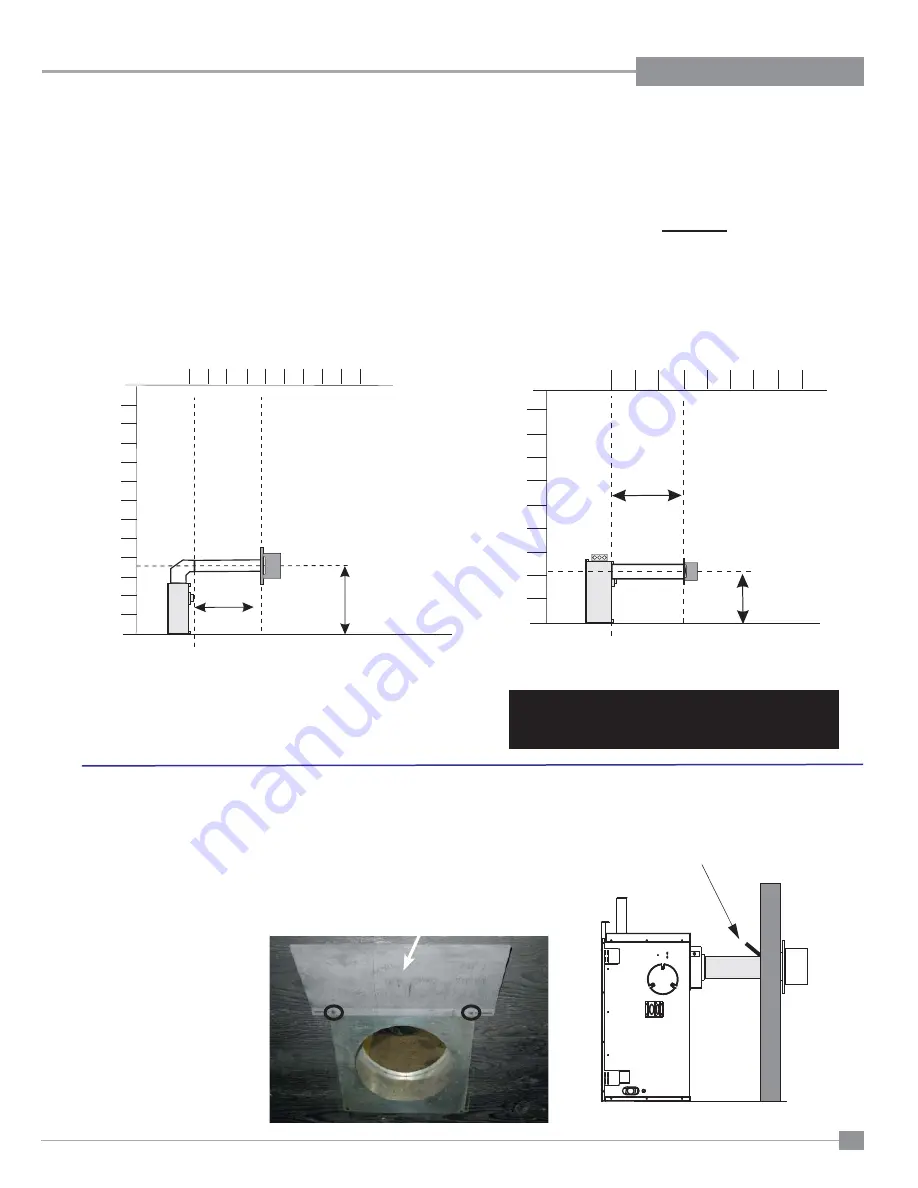
The diagrams show all allowable combinations of vent runs with 5" x 8" venting using the Regency direct vent system or rigid vent system.
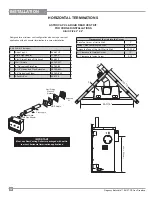
A vent guard should be used whenever the termination is lower than the specifi ed minimum or as per local codes.
For horizontal terminations the Regency Direct Vent Flex System may be used for installations upto a maximum
continuous
vent length of 10ft (3.0m).
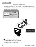
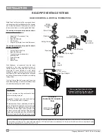
Note: Must use optional rigid pipe adaptor (Part # 770-994) when using Rigid Pipe vent systems.
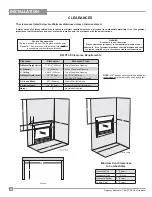
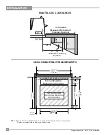
• Maintain clearance to combustibles.
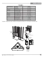
• Horizontal vent must be supported every 3 feet.
• Firestops are required at each
fl
oor level and whenever passing through a wall.
2
0
12
6
4
8
10
2
0
6
4
8
V
ertical
Height
(Feet)
Rigid
or
Flex
47-1/2"
(1.2m)
Horizontal (Feet)
Max. 36”(0.9m)
2
0
6
4
8
2
0
6
4
8
V
ertical
Height
(Feet)
28
-
1/2"(0.7m)
Horizontal (Feet)
Max. 36"(0.9m)
Vent Restrictor - Set 1
Factory Setting - No Restrictor Required
VENTING ARRANGEMENTS FOR HORIZONTAL TERMINATIONS
FLEX VENT OR RIGID PIPE 5" X 8"
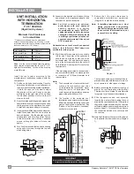
REAR VENTING DEFLECTOR INSTALLATION
FOR REAR VENTED HORIZONTAL TERMINATIONS
Rear Venting Defl ector
The Rear Vent Defl ector comes with the unit. When the unit is shipped
the defl ector is slightly tucked underneath the top nailing strips located
at the top of the fi rebox.
NOTE:
The Rear Venting Defl ector must be installed before the unit is
put in place.
IMPORTANT
Must use Rear Venting De
fl
ector packaged with unit in
rear vent horizontal termination applications.
Rear Venting
Deflector
1)
Secure the rear venting
defl ector to the wall thimble
using 2 screws as shown.
Ensure to use the same screw
holes as the wall thimble.

