background image

4

    | 

I1150 Regency Wood Insert


safety decal

This is a copy of the label that accompanies each 

I1150 Wood Insert

. We have printed a copy of 

the contents here for your review.

NOTE: 

  Regency  units  are  constantly  being 

improved.  Check the label on the unit and if 
there  is  a  difference,  the  label  on  the  unit  is 
the correct one.

Part #:  920-131

Colour:   Black on grey, except for selected items which are printed red.

Size: 

File is at 100%.   4" W x 10.7" H (excluding tear off

June 24/19:  Created decal

July 2/19:      Updated 'D' clearance

July 31/19: Updated as per Radu

LISTED FACTORY BUILT FIREPLACE INSERT

CERTIFIED FOR USE IN CANADA AND U.S.A.

MODEL: 

I1150

TESTED TO:

ULC S628-M93  / UL 1482-2011 (R2015)


DO NOT REMOVE THIS LABEL / NE PAS ENLEVER CETTE ÉTIQUETTE

531

COMPONENTS REQUIRED FOR INSTALLATION: 5.5" (140mm) or  6" (152mm)STAINLESS STEEL 

LINER LISTED CHIMNEY LINER.  

OPTIONAL COMPONENT: FAN PART#172-917, ELECTRICAL RATING: VOLTS 115, 60 HZ, 0.6 AMPS

DANGER: RISK OF ELECTRIC SHOCK. DISCONNECT POWER BEFORE SERVICING UNIT.

DO NOT REMOVE BRICKS OR MORTAR IN MASONRY FIREPLACE.  FOR USE WITH SOLID WOOD FUEL 

ONLY.  DO NOT USE GRATE OR ELEVATE FIRE.  DO NOT CONNECT THIS UNIT TO A CHIMNEY FLUE 

SERVING ANOTHER APPLIANCE. BUILD WOOD FIRE DIRECTLY ON HEARTH. OPERATE WITH FEED 

DOOR CLOSED, OPEN TO FEED FIRE ONLY.  REPLACE GLASS ONLY WITH CERAMIC GLASS (5MM).  

INSPECT AND CLEAN CHIMNEY FREQUENTLY. UNDER CERTAIN CONDITIONS OF USE CREOSOTE 

BUILD-UP MAY OCCUR RAPIDLY.  DO NOT OVERFIRE, IF INSERT GLOWS YOU ARE OVER-FIRING.

CAUTION: MOVING PARTS MAY CAUSE INJURY. DO NOT OPERATE UNIT WITH A

REMOVED PART OR PARTS.

MINIMUM CLEARANCES TO COMBUSTIBLE MATERIALS 

(MEASURED FROM INSERT BODY)

COMBUSTIBLE FLOOR MUST BE PROTECTED BY NON-COMBUSTIBLE MATERIAL EXTENDING (E) 

16 IN / 405MM TO  FRONT AND (G) 8IN / 205MM TO SIDES FROM FUEL DOOR. IN CANADA MUST 

EXTEND 18” TO FRONT.

THERMAL INSULATION WITH A R VALUE = 1.4 AT A DISTANCE OF 18" FROM FRONT OF DOOR 

OPENING FOR CANADA AND 16" FOR USA. IF UNIT RAISED 4.5" FROM FLOOR, NO THERMAL INSU-

LATION IS REQUIRED.

MANUFACTURED BY/ 
FABRIQUÉ PAR :
FPI FIREPLACE PRODUCTS 
INTERNATIONAL LTD.
6988 VENTURE ST.
DELTA, BC  V4G 1H4

HOT WHILE IN OPERATION

DO NOT TOUCH. KEEP CHILDREN, CLOTHING AND 

FURNITURE AWAY.

CONTACT MAY CAUSE SKIN BURNS. 

READ ABOVE INSTRUCTIONS.

APPAREIL CHAUD LORSQU’IL FONCTIONNE. 

NE PAS TOUCHER. GARDER À DISTANCE DES ENFANTS, DES 

VÊTEMENTS ET DU MOBILIER.  

TOUT CONTACT PEUT CAUSER DES BRÛLURES.   

LIRE LES INSTRUCTIONS CI-DESSUS.

ATTENTION / DANGER

ADJACENT SIDEWALL  A)  15in / 380mm

MANTEL 

B)  20n / 510mm

TOP FACING 

C)  14in / 355mm

SIDE FACING 

D)  0.5in / 13mm

(to side surround)

INSTALL AND USE ONLY IN ACCORDANCE WITH THE MANUFACTURER'S

INSTALLATION AND OPERATING INSTRUCTIONS.  INSTALL AND USE ONLY

IN MASONRY FIREPLACE OR FACTORY BUILT FIREPLACE.

CONTACT LOCAL BUILDING OR FIRE OFFICIALS ABOUT RESTRICTIONS AND

INSTALLATION INSPECTION IN YOUR AREA.


    JAN

    FEB


  MAR


  APR


  M

AY


 JUN


 JUL


AUG


SEPT


OCT


NOV 


DEC

2019

2020

2021

2022

2023

(Duplicate Serial #)

DA

TE OF MANUF

ACTURE / DA

TE DE F

ABRICA

TION

MADE

 IN

 CANADA

 / 

FAIT

 AU

 CANADA

A

D

B

C

MUR LA

TÉRAL

ADJACENT

PIÈCES OBLIGATOIRES POUR L’INSTALLATION : GAINE DE CHEMINÉE HOMOLOGUÉE EN ACIER 

INOXYDABLE DE 5,5 PO (140mm) ou  6 PO (152mm).  

PIÈCE EN OPTION : VENTILATEUR PIÈCE N

O

172-917

CARACTÉRISTIQUES ÉLECTRIQUES : 115 VOLTS, 60 HZ, 0,6 AMPS.

DANGER : RISQUE D’ÉLECTROCUTION. DÉBRANCHER LE COURANT AVANT DE PROCÉDER À L’EN-

TRETIEN DE L’APPAREIL.

NE PAS RETIRER LES BRIQUES OU LE MORTIER DU FOYER EN MAÇONNERIE. À UTILISER AVEC 

UN COMBUSTIBLE SOLIDE EN BOIS SEULEMENT. NE PAS UTILISER DE GRILLE NI SURÉLEVER LE 

FEU. NE PAS CONNECTER CET APPAREIL À UN CONDUIT DE CHEMINÉE DESSERVANT UN AUTRE 

APPAREIL. FAIRE UN FEU DE BOIS DIRECTEMENT SUR L’ÂTRE.  FAIRE FONCTIONNER L’APPAREIL 

AVEC LA PORTE DE CHARGEMENT FERMÉE, L’OUVRIR SEULEMENT POUR ALIMENTER LE FEU. 

REMPLACER LA VITRE SEULEMENT AVEC UNE VITRE EN CÉRAMIQUE (5MM). FAIRE INSPECTER 

ET RAMONER LA CHEMINÉE À INTERVALLES RÉGULIERS. ACCUMULATION RAPIDE DE CRÉOSOTE  

DANS CERTAINES CONDITIONS. NE PAS SURCHAUFFER : SI L’ENCASTRABLE EST ROUGEOYANT, 

L’APPAREIL SURCHAUFFE.

ATTENTION : LES PIÈCES AMOVIBLES PEUVENT ENTRAÎNER DES BLESSURES. NE PAS FAIRE 

FONCTIONNER L’APPAREIL SI UNE OU PLUSIEURS PIÈCES ONT ÉTÉ ENLEVÉES.

DÉGAGEMENTS MINIMAUX AUX MATÉRIAUX COMBUSTIBLES

(MESURES PRISES DEPUIS LE CAISSON DE L’ENCASTRABLE)

LE PLANCHER COMBUSTIBLE DOIT ÊTRE PROTÉGÉ PAR UN MATÉRIAU NON COMBUSTIBLE 

S’ÉTENDANT SUR (E) 16 PO / 405MM À L’AVANT ET SUR (G) 8 PO / 205MM ENTRE LES CÔTÉS ET LA 

PORTE DE CHARGEMENT DU COMBUSTIBLE. PROLONGEMENT SUR 18 PO À L’AVANT AU CANADA.

ISOLATION THERMIQUE AVEC UNE VALEUR R = 1,4 À UNE DISTANCE DE 18 PO DEPUIS L’AVANT DE 

L’OUVERTURE DE LA PORTE AU CANADA  ET 16 PO AUX ÉTATS-UNIS. SI L’APPAREIL EST SURÉLEVÉ 

À 4,5 PO DU SOL, AUCUNE ISOLATION THERMIQUE N’EST REQUISE.

MUR LATÉRAL ADJACENT          A) 15 po / 380 mm

MANTEAU 


  B) 20 po / 510 mm

PAREMENT SUPÉRIEUR          C) 14 po / 355 mm

PAREMENT LATÉRAL  

  D) 0,5 po / 13 mm

D’INSTALLATION ET D’UTILISATION DU FABRICANT. À INSTALLER ET À UTILISER UNIQUEMENT DANS 

UN FOYER EN MAÇONNERIE OU UN FOYER PRÉFABRIQUÉ.

CONTACTEZ LES AUTORITÉS LOCALES EN BÂTIMENT OU INCENDIE POUR CONNAÎTRE LES  RE-

STRICTIONS D’INSTALLATION ET LES RÈGLES D’INSPECTION DANS VOTRE RÉGION.

920-131

531

CERTIFIÉ CONFORME AUX NORMES 2020 DU U.S. ENVIRONMENTAL PROTECTION AGENCY EN MATIÈRE 
D'ÉMISSION DE PARTICULES DE BOIS EN UTILISANT LE BOIS DE CORDE. HOMOLOGUÉ AVEC LA 
ASTM E3053. MODÈLE REGENCY I1150 –1.7 G /H. CET APPAREIL DE CHAUFFAGE AU BOIS DOIT ÊTRE 
INSPECTÉ PÉRIODIQUEMENT ET RÉPARÉ POUR FONCTIONNER CORRECTEMENT. CONSULTER LE 
MANUEL D’INSTALLATION POUR PLUS D’INFORMATION. LA RÉGLEMENTATION FÉDÉRALE INTERDIT 
DE FAIRE FONCTIONNER UN TEL APPAREIL SI LES CONSIGNES D’UTILISATION CONTENUES DANS LE 
PRÉSENT MANUEL NE SONT PAS RESPECTÉES.

0219WN027S

U.S. ENVIRONMENTAL PROTECTION AGENCY CERTIFIED TO COMPLY WITH 2020 PARTICULATE EMIS-
SION STANDARDS USING CORD WOOD.”  TESTED TO ASTM E3053.  MODEL REGENCY I1150 – 1.7G /HR. 
THIS WOOD HEATER NEEDS PERIODIC INSPECTION AND REPAIR FOR PROPER OPERATION. CONSULT 
THE OWNER’S MANUAL FOR FURTHER INFORMATION. IT IS AGAINST FEDERAL REGULATIONS TO 
OPERATE THIS WOOD HEATER IN A MANNER INCONSISTENT WITH THE OPERATING INSTRUCTIONS IN 
THE OWNER’S MANUAL.

Copy of the I1150 Safety Decal

Summary of Contents for Cascades I1150

Page 1: ...G 1H4 920 132 Cascades I1150 Wood Insert 09 03 19 Owners Installation Manual Installer Please complete the details on the back cover and leave this manual with the homeowner Homeowner Please keep these instructions for future reference www regency fire com Tested by 0219WN027S ...

Page 2: ...n the building envelope It is against federal regulation to operate this wood heater in a manner inconsistent with operating instructions in this manual This heater is designed to burn natural wood only Higher efficiencies and lower emissions generally result when burning air dried seasoned hardwoods as compared to softwoods or to green or freshly cut hardwoods DO NOT BURN Treated wood Lawn clippi...

Page 3: ... a Masonry Fireplace 10 Installation Into a Factory Built Fireplace 10 Faceplate Trim Optional 11 Bottom Faceplate Fan Support Installation 11 Fan Blower 15 Brick Installation 16 Baffle installation 17 Glass Replacement 18 Wood door handle assembly 19 Stainless steel smoke deflector installation 20 Seasoned wood 21 Primary air operating handle 21 Operation Operating Instructions 22 Draft Control 2...

Page 4: ...IÈCES OBLIGATOIRES POUR L INSTALLATION GAINE DE CHEMINÉE HOMOLOGUÉE EN ACIER INOXYDABLE DE 5 5 PO 140mm ou 6 PO 152mm PIÈCE EN OPTION VENTILATEUR PIÈCE NO 172 917 CARACTÉRISTIQUES ÉLECTRIQUES 115 VOLTS 60 HZ 0 6 AMPS DANGER RISQUE D ÉLECTROCUTION DÉBRANCHER LE COURANT AVANT DE PROCÉDER À L EN TRETIEN DE L APPAREIL NE PAS RETIRER LES BRIQUES OU LE MORTIER DU FOYER EN MAÇONNERIE À UTILISER AVEC UN C...

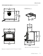
Page 5: ...nsert 5 dimensions 1 1 2 38mm with standard flue adaptor 6 152mm Diameter STANDARD FLUE ADAPTOR Regency Inserts are designed to use either a 5 5 140mm or 6 152mm flue Measurement from back of faceplate to fuel door opening ...

Page 6: ... Insert dimensions 1 1 2 38mm 455 with offset flue adaptor 6 152mm Diameter OFFSET FLUE ADAPTOR Regency Inserts are designed to use either a 5 5 140mm or 6 152mm flue Measurement from back of faceplate to fuel door opening ...

Page 7: ...nufacturer s installation and operating instructions 2 Check your local building codes Building Inspection Department You may require a permit before installing your insert Be aware that local codes and regulations may override some items in the manual WARNING Careless installation is the major cause of safety hazard Check all local building and safety codes before installation of unit 3 Notify yo...

Page 8: ...ion and hearth will meet the standards for clear ance to combustibles Your hearth extension must be made from a non combustible material Extending 16 for US and 18 for Canada measured from the fuel loading door Unit I1150 Adjacent Side Wall to Side A Mantel to Top of Unit B Top Facing to Top of Unit C Side Facing D Minimum Hearth Extension E Minimum Hearth Side Extension F To Top of Unit G 15 381m...

Page 9: ...the rear of the unit into the fireplace See Diagram 3 En sure that the unit is centered in the existing fireplace and lined up with the flue adaptor 4 Slide the unit back until the flue adaptor is slightly engaged 5 At this point it is recommended to level the unit and ensure that the leveling bolts rest on the surface of the fireplace This will keep the adaptor from binding as the unit is slid in...

Page 10: ...pproximately the alignment of the flue liner with the position of the smoke outlet hole on the insert to check for possible offset If an offset is required use the appropriate offset adaptor in your installation 6 Oncetheaboveitemshavebeenchecked slide your insert into position after first positioning and securing the flue liner to the offset adaptor Attachtherodtotheadaptorandslidetheadap tor ont...

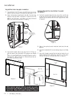
Page 11: ...d Reproductive Harm www P65Warnings ca gov FACEPLATE TRIM FAN OPTIONAL BOTTOM FACEPLATE FAN SUPPORT INSTALLATION Regular Faceplate Dimensions shown with bottom faceplate fan support attached Oversize Faceplate Dimensions shown with bottom faceplate fan support attached 38 965mm 44 1118mm 26 3 8 670mm 30 3 8 772mm 34 3 8 874mm 38 3 8 975mm 8 203mm maximum maximum 8 203mm 38 965mm 44 1118mm 26 3 8 6...

Page 12: ...older can then be slid into the tool bracket as shown Digital monitor operating door tool bracket Tool holder slid into tool bracket Tool holder Diagram 2A Rear View 4 Position the assembled faceplate side and top to the insert Ensure to align the draft rod into the opening of the faceplate as well as the side faceplate slots with the bolts in the mounting brackets as shown in Diagram 3 5 Measure ...

Page 13: ... completed faceplate trim assembly to the insert Ensure to align the side faceplate slots with the hex bolts in the mounting brackets and tighten to secure in place Secure the Regency logo plate to the bottom of the faceplate Diagram 5 Diagram 6 Shown with Optional Bottom Faceplate Regular Oversize Faceplate Trim Installation Black Trim included with Regular Oversize Faceplate or Bottom Faceplate ...

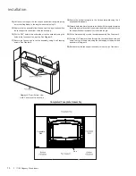
Page 14: ...g screws See Diagram 9 Diagram 9 Rear Bottom View Note Fan not exactly as shown 18 Secure the bottom faceplate to the 3 sided faceplate using the 4 supplied bolts washers 19 Discard both side trims that were included with the regular oversize faceplate and replace with the new extended trims supplied with the fan support bottom faceplate Cut to desired length 20 Fit the trim assembly over the face...

Page 15: ...l wires prior to disconnec tion when servicing controls Wiring errors can cause improper and dangerous operation WARNING Electrical Grounding Instructions This appliance is equipped with a three pronged grounding plug for your protection against shock hazard and should be plugged directly into a prop erly grounded three prong receptacle Do not cut or remove the grounding prong from this plug I1500...

Page 16: ...itions Do not use a grate LyTherm sheet Order of firebrick install a Rear Firebrick b Firebox floor install brick over LyTherm Sheet c Right and left side Firebricks Fire bricks Size 1 4 1 4 x 7 2 4 1 2 x 7 3 9 x 4 1 2 4 9 x 2 5 3 1 2 x 4 1 2 6 4 1 4 x 8 7 3 1 2 x 2 1 4 1 4 6 5 3 7 2 ITEM NO PART NUMBER QTY DESCRIPTION 7 RD 14287 2 3 500 x2 2500 BRICK 6 RD 14286 2 4 250 x 8 000 x 30 DEG BRICK 5 80...

Page 17: ...e stainless steel smoke deflector See instruc tions in this manual 2 Remove the front secondary air tube with pliers as shown below Note It will be easier to remove the air tubes by removing both the bottom right base brick and right side wall brick 5 Install left and right baffle brackets installation of left baffle bracket shown below Baffle installation 4 Install the right and left side baffles...

Page 18: ...your glass by impact purchase your replacement from an authorized Regency dealer only Remove the door from the stove and remove the screws securing the glass retainer Position the glass in the door make sure that the glass gasketing will properly seal your unit and replace the retainer it should rest on the gasket not the glass Tighten securely but do not wrench down on the glass as this may cause...

Page 19: ... a tight seal If door is too tight a washer can be removed Recheck door to ensure there is still a tight seal The handle should be approxi mately in the 8 o clock position when door is fully closed Diagram 3 2 Place the door onto the hinges and then place the door handle through the opening on the door as shown in Diagram 2 Diagram 1 Diagram 2 Diagram 3 Nuts Cam Door Handle Washers Spacer Re assem...

Page 20: ...off both bolts and slide deflector downward push deflector to the back wall of the unit and manoeuver out Install new deflector and hand tighten bolts Ensure positive location of the deflector prior to hand tightening WARNING Operation of the unit with out proper installation of smoke deflector will void warranty Smoke deflector installed with 2 bolts Note This is a cutaway view from the back of t...

Page 21: ...d may take a minimum of a full year to dry enough Drying may also take longer in damp climates There are a few ways to tell if wood is dry enough to burn efficiently Use as many indicators as possible to judge the dryness of the firewood your are considering Here are ways to judge firewood moisture Using a moisture meter select the species of fuel and then penetrate the pins into a split piece Ide...

Page 22: ...G Never build a roaring fire in a cold stove Always warm your stove up slowly 3 During the first few fires keep the combustion rate at a moderate level and avoid a large fire Only after 5 or 6 such fires can you operate the stove at its maximum setting and only after the metal has been warmed Always build up the fire slowly 4 For the first few days the stove will give off an odour from the paint T...

Page 23: ...our stove 4 If you have smoke detectors prevent smoke spillage as this may set off a false alarm 5 Do not overfire heater If the chimney connector flue baffle or the stove top begin to glow you are over firing Stop adding fuel and close the draft control Over firing can cause extensive damage to your stove including warping and premature steel corrosion Over firing will void your warranty 6 Do not...

Page 24: ...ed before the burning season and as necessary during the season as creosote deposits may build up rapidly Moving parts of your stove require no lubrication 4 A small hot fire is preferable to a large smoul dering one that can deposit creosote within the system 5 The chimney and chimney connector should be inspectedatleastonceeverytwomonthsduring the heating season to determine is a creosote buildu...

Page 25: ... into hole on left side air channel Align tab on right side air channel with notch on right hand end of air tube Firmly grip center of air tube with vise grips use hammer to tap vise grips from left to right until the tube bottoms out into the air channel on right Latch Adjustment Thedoorlatchmayrequireadjustmentasthedoorgasketmaterialcompresses after a few fires Removal of the spacer washer shown...

Page 26: ...ir tubes vermiculite baffles see manual for details 2 Loosen the two 7 16 bolts nuts to remove replace vertical baffle 3 Repeat steps to install new vertical deflector NOTE ENSURE BAFFLE IS PUSHED UP AS FAR AS POSSIBLE TIGHT TO TOP OF FIREBOX Vertical Deflector Remove 2 front air tubes Slide right down to remove Reverse to replace ...

Page 27: ...he paper should not pull out easily if it does try adjusting the door latch if that doesn t solve the problem replace the door gasket Check and lubricate door hinge latch Use only high temperature anti seize lube ie never seize Check glass for cracks Replace if required Clean blower motor Disconnect power supply Remove and clean blower DO NOT LUBRICATE Inspect and clean chimney Annual professional...

Page 28: ...el Accent 12 846 306 Replacement Glass Includes Gasket Size 9 1 8 X 15 5 8 13 936 241 Replacement Glass Gasket Sold per foot 4 Feet required 14 846 570 Door Gasket Repair Kit 15 075 077F Glass Retainer 16 948 920 Black Hinge Caps Set of 2 16 948 079BN Nickel Hinge Cap Each 17 650 084 Door Spacer Each 18 075 064 Andiron Bracket Each 19 075 063F Andiron Each 20 075 040 Side Baffle Cover Each 21 075 ...

Page 29: ...I1150 Regency Wood Insert 29 parts list main assembly 1 22 2 18 21 21 4 17 16 8 5 26 6 3 19 24 9 11 25 9 15 13 10 14 12 7 20 20 27 ...

Page 30: ...x 8 000 x 30 DEG BRICK 5 802 147 1 3 500 x 4 500 BRICK 4 802 152 2 2 000 x 9 000 BRICK 3 902 111 3 9 000 x 4 500 STANDARD BRICK 2 RD 14289 2 4 500 x 7 000 BRICK 1 RD 14288 2 4 250 x 7 000 BRICK brick panels 172 960 I1150 Brick Kit Complete Fire bricks Size 1 4 1 4 x 7 2 4 1 2 x 7 3 9 x 4 1 2 4 9 x 2 5 3 1 2 x 4 1 2 6 4 1 4 x 8 7 3 1 2 x 2 1 4 ...

Page 31: ... 64 65 60 62 61 64 65 60 62 58 59 60 Faceplate Right Side Regular Oversize 61 Faceplate Left Side Regular Oversize 62 Faceplate Top Regular Oversize 64 Bottom 1 Piece Faceplate 65 Fan Support N S 171 570 Black Perimeter Trim Black Regular Faceplate N S 171 572 Black Perimeter Trim Black Oversize Faceplate N S 948 223 Regency Logo Plate N S 171 526 Faceplate Mounting Brackets Each N S 171 546 Facep...

Page 32: ... 1 Catalyst Combustor 10 Years Prorated Venting Chimney 1 Screens 1 See specific warranty details in regards to the catalyst combustor in unit manual Conditions Warranty protects against defect in manufacture or FPI factory assembled components only unless herein specified otherwise Any part s found to be defective during the warranty period as outlined above will be repaired or replaced at FPI s ...

Page 33: ...ect chimney components including but not limited to cap size or type operator error abuse misuse use of improper fuels such as unseasoned cordwood mill ends construction lumber or debris off cuts treated or painted lumber metal or foil plastics garbage solvents cardboard coal or coal products oil based products waxed cartons compressed pre manufactured logs kiln dried wood lack of regular maintena...

Page 34: ...o the above limitations or exclusions may not apply to you Customers located outside the U S should consult their local provincial or national legal codes for additional terms which may be applicable to this warranty How to Obtain Warranty Service Customers should contact the authorized selling dealer to obtain all warranty and service In the event the authorized selling dealer is unable to provid...

Page 35: ... for us to serve you better Warranty Registration Form or Register online immediately at the above Web Site Warranty Details Serial Number required Purchase Date required mm dd yyyy Product Details Product Model required Dealer Details Dealer Name required Dealer Address Dealer Phone Installer Date Installed mm dd yyyy Your Contact Details required Name Address Phone Email For purchases made in CA...

Page 36: ...36 I1150 Regency Wood Insert ...

Page 37: ...I1150 Regency Wood Insert 37 notes ...

Page 38: ...38 I1150 Regency Wood Insert notes ...

Page 39: ...I1150 Regency Wood Insert 39 ...

Page 40: ..._____________________________________________ Phone ____________________________________________________________ Date Installed _______________________________________________________ Serial No ___________________________________________________________ Printed in Canada Regency is a trademark of FPI Fireplace Products International Ltd Copyright 2019 FPI Fireplace Products International Ltd All r...

Reviews: