background image

28

     | 

City Series ACB60E

installer's  information

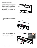
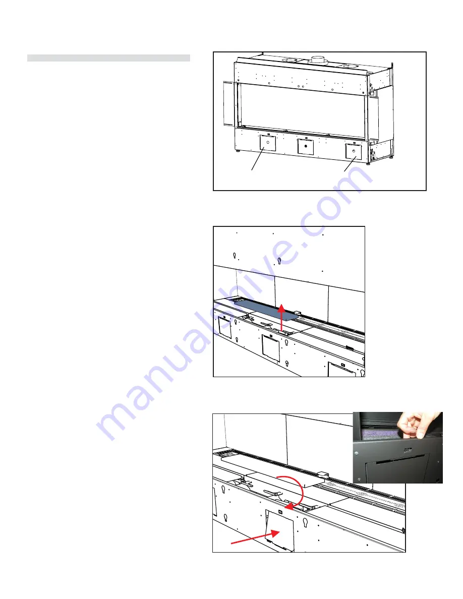
Access Panel Removal

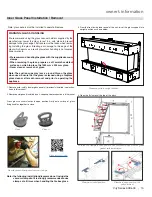
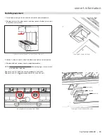
The front access panels (x3) and one (x1) on the right side 
(facing unit front) may be removed for ease of hooking up gas 
and electrical--prior to finishing. Once complete ensure that the 
access panel is reinstalled prior to any finishing. 
See locations in diagram to the right.

Note:  Once  the  finished  material  is  installed,  these  access 
panels are no longer accessible.

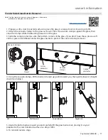
Access panel removal

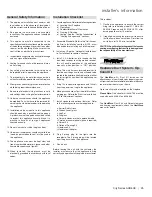
The  front access  panels  (x3)  may be removed  for ease  of 

hooking up gas  and electrical--prior  to finishing. Once  complete 

ensure  that the access  panel is reinstalled  prior to any finishing. 

See  locations  in diagram  to the right.

Note:  Once  the finished material  is installed,  these  access

panels  are  no longer accessible.

tooltip

Gas connection

Electrical

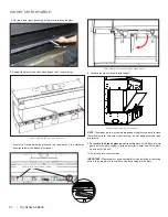
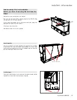
1.  Identify access  panel to be removed,  remove  corresponding

outer trim panel by lifting up and off (centre  panel shown

below).

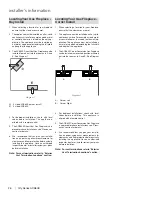
2.  From  inside  the unit--push in tab to release  the access

panel at the top.

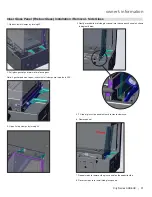
3.  Push  the access  towards the inside  of the unit, lift up from 

the bottom to release  bottom tabs,  when clear,  lift out of unit.

4. Reverse  steps  to reinstall  access  panel.

tooltip

tooltip

1.  Identify access panel to be removed, remove corresponding 

outer trim panel by lifting up and off (centre panel shown 
below).

2.  From  inside  the  unit—push  in  tab  to  release  the  access 

panel at the top.

3.  Push the access towards the inside of the unit, lift up from 

the bottom to release bottom tabs, when clear, lift out of unit.

4. Reverse steps to reinstall access panel.

Summary of Contents for City ACB60E

Page 1: ... your gas supplier from a neighbour s phone Follow the gas supplier s instructions If you cannot reach your gas supplier call the fire department Installation and service must be performed by a qualified installer service agency or the gas supplier WARNING FIRE OR EXPLOSION HAZARD Failure to follow safety warnings exactly could result in serious injury death or property damage 920 317a FPI FIREPLA...

Page 2: ...nd charm of a wood fireplace at the flick of a switch The ACB60E City Series is approved by Intertek for both safety and efficiency City Series appliances also bear Regency s mark signifying our promise to provide you with economy comfort and security for many trouble free years to follow Please take a moment to acquaint yourself with the instructions in this manual and the many features of your R...

Page 3: ...ff Switch and Battery Holder Installation 49 Exterior Flue Termination Locations 50 Clearances 51 127 mm x 203 mm Rigid Pipe Cross Reference Chart only 52 Vent Restrictor Position 54 Venting Introduction 55 Venting Arrangement for Horizontal Terminations 55 Horizontal Terminations Flex Vent 127 mm x 203 mm 56 Horizontal Terminations Rigid Pipe 127 mm x 203 mm 57 Horizontal Terminations Rigid Pipe ...

Page 4: ...nce Do not touch any electric switch Immediately call your gas supplie If you cannot reach your gas sup B Do not use this appliance if any part appliance and to replace any part o This appliance needs fresh air for safe and ventilation air STO 1 Ensure the Main switch is in the ON posi 2 Press and release the ON OFF button on using the remote the unit can also be tu 3 After approximately 4 seconds...

Page 5: ...leveling legs fully inserted Height may vary depending on the length of the leveling legs when unscrewed or extended Note These units are non load bearing ALL PICTURES DIAGRAMS SHOWN THROUGHOUT THIS MANUAL ARE FOR ILLUSTRATION PURPOSES ONLY ACTUAL PRODUCT MAY VARY DUE TO PRODUCT ENHANCEMENTS ...

Page 6: ...7 mm 1837 mm 330 mm 185 mm 990 mm 279 mm 466 mm 263 mm 1810 mm 421 mm 515 mm Dimensions Corner Install Note Height dimension is taken with leveling legs fully inserted Height may vary depending on the length of the leveling legs when unscrewed or extended Note These units are non load bearing ALL PICTURES DIAGRAMS SHOWN THROUGHOUT THIS MANUAL ARE FOR ILLUSTRATION PURPOSES ONLY ACTUAL PRODUCT MAY V...

Page 7: ... Side Left Side 1 3 8 2 1 2 33 1 8 5 29 1 4 2 1 2 1 3 8 16 3 8 OPENING AT UNIT BASE 20 7 1 8 11 3 8 GAS VALVE FRONT OF UNIT BACK OF UNIT 3 3 4 7 5 8 5 6 3 4 6 3 4 5 7 5 8 3 7 8 LEFT SIDE RIGHT SIDE 35 mm 64 mm 841 mm 743 mm 127 mm 35 mm 64 mm 508 mm 289 mm 181 mm 416 mm 171 mm 127 mm 194 mm 98 mm 95 mm 194 mm 127 mm 171 mm ...

Page 8: ...ns Electrical Connection Bottom of Unit Electrical Connection Side of Unit 3 3 4 7 5 8 5 6 3 4 RIGHT SIDE 16 3 8 OPENING AT UNIT BASE 20 7 1 8 11 3 8 FRONT OF UNIT BACK OF UNIT 194 mm 127 mm 171 mm 95 mm 508 mm 289 mm 181 mm 416 mm ...

Page 9: ...AY FROM HOT SURFACES Important Message SAVE THESE INSTRUCTIONS City Line direct vent fireplaces must be installed in accordance with the instructions in this manual carefullyreadthemfirst Consultthe authorityhaving jurisdiction in your area to determine the need for a permit prior to starting the installation It is the responsibility of the installer to ensure this fireplace is installed in compli...

Page 10: ...nd contract at different rates resulting in some cracking and ticking sounds that will be heard throughout the cycling process During the first few fires a white film may developontheglassfrontaspartofthecuring process Theglassshouldbecleanedafterthe unit has cooled down or the film will bake on and become very difficult to remove Use a non abrasive cleaner and DO NOT ATTEMPT TO CLEAN THE GLASS WH...

Page 11: ...iding the battery holder switch to the ON position if equipped Note The first try for ignition will last approximately 60 seconds If there is no flame ignition rectification the board will stop sparking for approximately 35 seconds After wait time the board will start second try for ignition by sparking for approximately 60 seconds If there is still no positive ignition the board will go into lock...

Page 12: ...mmediately call your gas supplier from a neighbors phone Follow the gas supplier s instructions If you cannot reach your gas supplier call the fire department B Do not use this appliance if any part has been under water Immediately call a qualified service technician to inspect the appliance and to replace any part of the control system and any gas control which has been under water This appliance...

Page 13: ...functions 5 Accent light modulation 6 levels 6 Split flow valve 7 Comfort Fan speed modulation 6 levels This feature is not available on any Hampton models IMPORTANT The Proflame Transmitter 2 is an integrated part of the Proflame 2 System which consists of these elements Proflame 2 Transmitter to be used in conjunction with Integrated Fireplaces Control Proflame 2 IFC The Proflame Transmitter use...

Page 14: ...until the flame is turned off The Up Arrow Key will increase the flame height each time it is pressed If the Up Arrow Key is pressed while the system is on but the flame is off the flame will come on in the high position Fig 7 8 A single beep will confirm reception of the command Fig 7 Fig 8 Room Thermostat Transmitter Operation The Remote Control can operate as a room thermostat The thermostat ca...

Page 15: ...speed can be adjustedthroughsix 6 speeds ToactivatethisfunctionusetheModeKey fig 1 to index to the fan control icon Fig 13 Use the Up Down Arrow Keys fig 1 to turn on off or adjust the fan speed fig 14 A single beep will confirm reception of the command Figure 13 Figure 14 Remote dimmer control Light The auxiliary function controls the AUX power outlet by the dimmable light control To activate thi...

Page 16: ...y changed from an intermittent pilot ignition system IPI to a continuous pilot ignition system CPI by using remote control as noted above The benefits of having as CPI are as follows Keeps venting primed for trouble free start up under colder weather conditions or inversions Keeps the unit glass warm which decreases the amount of condensa tion on start up Provides owners with flexibility to choose...

Page 17: ...e corner protectors onto the bottom corners of the glass If you don t have these place a soft cloth or piece of cardboard under the glass barrier to protect the corners during removal 4 Using the vacuum clamps lift the barrier straight up pull it toward you then gently lower it straight down see below Open Vacuum clamps Closed Vacuum clamps Corner protector Corner protector Lift Pull forward Lower...

Page 18: ...oward you Counter clockwise angles barrier in towards the unit Slide the screwdriver straight up at the two indicator slots Glass Barrier Adjustment If side glass height needs adjustment follow the next step To adjust the side glass remove the screws at the top of the panel and move the glass up or down When the glass is in the correct position replace and tighten the screws ...

Page 19: ...lamps When removing the glass prepare a soft scratch resistant surface on which to place the 1554 mm x 504 mm glass Never clean or remove hot glass Note The suction cups may leave a round film on the glass when used Ensure that the glass is cleaned using a fireplace glass cleaner after each removal and prior to operating the appliance Note glass panels must be installed to operate fireplace 4 Open...

Page 20: ... on support Lower clamps x9 in open position Push down on levers to lower glass panel Gasket pad NOTE The firebox glass may remain propped on the glass supports to clean the interior surface Use care when cleaning do not apply excessive force or pressure 9 To remove the firebox glass panel from the unit tilt the glass forward gently onto the glass supports grip both suction clamps and lift the gla...

Page 21: ...lass Note if gasket pad won t open check that all clamps are turned a full 90 3 Open 2x top clamps by turning 90 4 Gently move bottom of side glass panel into the support channel as shown in diagram below 5 Tilt top of glass side panel outward to create clearance 6 Remove panel 7 Repeat steps to remove side glass panel on the opposite side 8 Reverse steps to re install side glass panels ...

Page 22: ...tions in this manual 3 Install glass stopper if desired by sliding stopper assembly between unit and panel the stopper assembly will attach to the unit via a magnet adjust position of glass stopper is required 2 Slide backwall outer panel behind glass stopper bracket if installed 1 Install glass stopper if desired by sliding down the outside of the outer side panel WARNING DO NOT SPRAY AEROSOLS IN...

Page 23: ...ner light cover and remove 4 Replace bulb and reverse steps to complete procedure NOTE Do not handle bulb with bare hands Use packaging or a tissue to hold new bulb when replacing Regency Part 911 208 Oven Lamp Assembly G9 240V 25W Regency Part 911 300 Replacement Bulb G9 240 Volt 25 watt Light are located behind the front face of the unit Inner light covers shown from below Inner light covers clo...

Page 24: ...talledintothedoorframe Reinstallasper GlassInstallationinthe GlassInstallation section REPLACEMENT GLASS ACB60E Outer Safety Glass Front Tempered Part 940 511 P Outer Safety Glass Right Side Tempered Part 940 509 P Outer Safety Glass Left Side Tempered Part 940 510 P Inner Glass Front Ceramic Part 940 507 P Inner Glass Side Ceramic Part 940 508 P Maintenance Instructions 1 Always turn off the gas ...

Page 25: ...s firing correctly and operation fully explained to customer General Safety Information 1 The appliance installation must conform with local codes or in the absence of local codes withthecurrentInstallationandBuildingCodes 2 See general construction and assembly instructions The appliance and vent should be enclosed 3 This appliance must be connected to the specifiedventandterminationcaptotheoutsi...

Page 26: ...tions refer to Exterior Vent Termination Locations section E Diagram 1 D 3 sided ACB60E corner install E 3 sided ACB60E Locating Your Gas Fireplace Corner Install 1 When selecting a location for your fireplace ensure that the clearances are met 2 The appliance must be installed on a flat solid continuous surface For example a wood metal or concrete floor or in a raised on the wall ap plication The...

Page 27: ...uds tooltip Leveling legs Leveling Legs There are four levelling legs two on each side that can be adjusted with the supplied tool found in the manual package if required tooltip Remove the screws securing the unit to the pallet Due to the size and weight 208 kg shipping weight of the ACB60E lifting and moving the unit will require 4 people Place a length long enough to get a solid grip on each si...

Page 28: ...t Note Once the finished material is installed these access panels are no longer accessible tooltip Gas connection Electrical 1 Identify access panel to be removed remove corresponding outer trim panel by lifting up and off centre panel shown below 2 From inside the unit push in tab to release the access panel at the top 3 Push the access towards the inside of the unit lift up from the bottomto re...

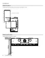
Page 29: ...wall Minimum F Alcove Depth 889 mm Front to Unit Maximum G Convection Air Outlet Opening Offset min 50 mm Max offset from top of chase enclosure H Convection Air Outlet 1161 square centimeters I Enclosure Depth min 516 mm Minimum inside dimensions J Opening Height 457 mm Bottom Top of Fireplace Opening K To Ceiling min all 3 sides 44 mm To Top of Ceiling L Chase Enclosure min 2064 mm From base of ...

Page 30: ...op opening Full framing with vents in front 2 sides or top Full framing with low vents in front or 2 sides Full framing with vents in front or 2 sides C I A1 A D L J H L I C D A1 A J G G H H H I C G A A1 G D J L H H I A D C J G G L H H A1 opening opening opening opening ...

Page 31: ...n in illustration Clearances will be the same for the right hand side Clearance single sided Dimension Measured From A Mantel Height min Top of Fireplace Opening B Opening Height 457 mm Bottom Top of Fireplace Opening C From Floor min 260 mm Bottom of Fireplace Opening D Sidewall on one side min 991 mm Side of Fireplace Opening E Mantel Depth max Front of Fireplace Opening F Alcove Depth 889 mm Fr...

Page 32: ...t facing are shown in the diagram on the right Mantel Leg Clearances Combustible mantel leg clearances as per diagram 51 305 152 102 203 254 0 356 229 mm 459 mm 254 508 660 Top of Fireplace Opening 305 mm 13 mm Drywall wood wood panel etc 133 mm To Bottom of Fireplace Opening 0 12 MANTEL LEG 0 305 mm ...

Page 33: ...is required for the convection air outlet to cool the enclosure Ensure clearances for Convection Air Outlets are met SeeclearancesACB60Einthis manual as there are different methods as to how this can be achieved Note Thisappliancemustbe installed on a solid surface such as a plywood floor which must be the full width and depth of the appliance Ensure that the wood base that the appliance will sit ...

Page 34: ...full width and depth of the appliance Framing Dimensions Description Corner Kit A Framing Height 1137 mm B Framing Width 1810 mm C Framing Depth 516 mm D Unit Base to Top Enclosure Min 2038 mm G Vent Centerline Height 1478 mm NOTE Unit cannot be load bearing All finishing materials must be supported by the framing Note Unit must be installed onto a solid back wall do not install directly onto stud...

Page 35: ...nce must be in stalled on a level and solid surface such as a plywood floor which must be the full width and depth of the appliance Framing Dimensions Description Corner Kit A Framing Height 1137 mm B Framing Width 1810 mm C Framing Depth 516 mm D Unit Base to Top Enclosure Min 2038 mm G Vent Centerline Height 1478 mm Note Unit must be installed onto a solid back wall do not install directly onto ...

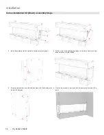
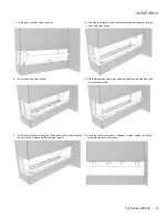
Page 36: ...m guide for left or right install to the outer side panel 3 Screw removable trim on and bend tabs closest to the finishing trim inwards 90 degrees 4 Slide outer side panel down onto the two screws in the firebox body Tighten screws with screwdriver 5 Screw in the three self tapping screws at the top of the outer side panel to attach it to the firebox 6 Unit can be placed in framing and finishing m...

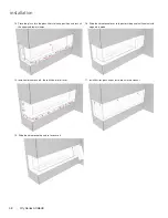
Page 37: ... firebox and then pushing them in 8 Install lower inner liner panels 10 Install the inner panel for the corner conversion by wedging it into the inner lower liner panels 12 Once the inner side panel is wedged in place tighten the hanger screws for the back liner panels 11 Slide the inner side panel in by wedging it between the side glass and the back liner panels 2 CB60E CORNER ...

Page 38: ...n and lock all the upper and lower clamps 14 Install outer liner panels there will be two left over 15 Slide the corner panel up and in to secure it 16 Slide the corner panel over to the outer side panel until contact with magnets is made 17 Install barrier glass as per instructions in the manual 3 CB60E CORNER ...

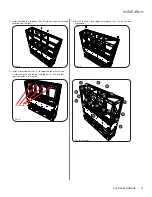
Page 39: ... assembling 2x Part B with 2x Part H with 8 screws installed from back of frame 2 Install the frame assembled in Step 1 onto the back of the unit as shown above with 2 screws on each side 3 Place unit against wall in desired location Level the unit by adjusting 4 leveling bolts on unit 4 Install venting before proceeding further with framing kit construction Refer to manual for venting instruction...

Page 40: ...pper and lower Part B of the back frame with 2 screws each each as shown Before installing Part I turn it so that the side screw holes are on the lower end next to lower Part B 7 Attach the 4 x end pieces Part J to the upper and lower Part B of the back frame with two screws each 8 Attach 2 x Part G to the previously installed Part J parts with 2 screws at each end 9 Attach end cross braces Parts ...

Page 41: ...all 4 horizontal mid braces Part K with one screw on each end installed from the top 12 Install 4 front supports Part C to upper and lower Part A with 2 screws on each end Before installing Part C turn it so that the screw holes are at the top 13 Install 2 top and 2 inner diagonal supports Part D with 2 screws at each end Part K Part D Part ID overview Part C screw holes ...

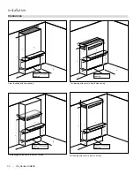
Page 42: ...al Finishing material Opening for vent 76mm 89mm Min 1530 mm Chase vent is installed after finishing material Framed opening must be between 76 mm and 89mmtall and at least 1530 mm wide to accommodate the chase vent The top of the chase vent opening must be 51 mmor less from the top of the chase enclosure Framed opening must be between 76 mm and 89 mm tall and at least 1530 mm wide to accommodate ...

Page 43: ...ontheloweraccesscoverpanel Longerscrewsmaypenetrategaslineordamagevalveorelectricalcomponents Note It is acceptable to use a high temperature silicone sealant to adhere plasterboard to lower access cover panel The appliance is designed to be used with a minimum 13 mm wall sheathing materials such as plasterboard plywood wood composites or non combustible materials Thicker materials may be used Ref...

Page 44: ...he enclosure to over heat Note that in all applications while there is a zero clearance to combustibles to the unit all clearances to combustibles from the venting inside the chase still applies Please see venting clearances in the specific product manual 4 Combustiblematerial plasterboard wood woodpanels etc maybebrought up to the appliance top bottom and sides 5 Ensure that the material being us...

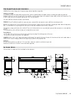
Page 45: ...City Series ACB60E 45 installation 4 cm x 9 cm shown Max 4 cm x 14 cm 51 mm 1161 cm2 min 419 mm 1328 mm 13 mm 914 mm 133 mm 1161 cm2 min Typical Installations Flush Install Recessed Install ...

Page 46: ...he appliance It must be secured to framing The TV depicted in the picture may need to be higher depending on the style of TV mounting bracket used 51 mm 1161 cm2 min 419 mm 1328 mm 13 mm 51 mm 1161 cm2 min 419 mm 13 mm Max 4 cm x 14 cm Typical Installations Flush TV with Hearth Maximum TV Recess ...

Page 47: ...surface Recess Install Example Flush Install Example Finish up to trim on all 4 sides Loosen screws using supplied Offset Screwdriver and remove bottom and side trim pieces Front edge of side liner panels must not be covered by finishing material or removal of the Firebox Glass will not be possible Bottom edge should be flush with top surface of Inner Liner Panel ...

Page 48: ...tlet s Regency Chase Vent Dimensions 76 mm x 1524 mm 1161cm2 Custom chase vent Example dimensions 63 5 mm x 1829 mm 1161cm2 Reveal at the chase top Example dimensions 44 mm x 2845 mm 1264cm2 Venting into an adjacent room Minimum 288in2 Note An adjacent room cannot be a garage closed in carport Chase Venting Note The enclosure opening cannot be any lower than 0 51 mm from the top of the enclosure f...

Page 49: ...nstalled prior to finishing 3 Connect the 6 pin connector to the back of the Battery Holder 4 Install the Battery Holder in the Low Voltage Junction box 5 Insert the 4 AA type batteries in the battery compartment with the correct polarity 6 Place the slider into the cover plate 7 Put the Battery Holder switch in the OFF position to allow correct lineup for slider switch 8 Make sure the Battery Hol...

Page 50: ...50 City Series ACB60E installation Exterior Flue Termination Locations FIGURE 6 2 in part LOCATION OF FLUE TERMINALS OF BALANCED FLUE AS NZ 5601 ROOM SEALED FAN ASSISTED OR OUTDOOR APPLIANCE ...

Page 51: ...s over 250MJ h input 1500 1500 All fan assisted flue appliances in the direction of discharge 1500 k From a mechanical air inlet including a spa blower 1500 1000 n Vertically below an openable window non mechanical air inlet or any other opening into a building iwth the exception of sub floor ventilation Space heaters up to 50MJ h input 150 150 Other appliances up to 50 MJ h input 500 500 Applianc...

Page 52: ...DVA DC Cathedral Support Box 58DVA CS Wall Support Band 58DVA WS Offset Support 58DVA ES Wall Thimble Black 58DVA WT Wall Thimble Support Ceiling Support 58DVA DC Firestop Spacer 58DVA FS Trim Plate Black 58DAV WFS 127 MM X 203 MM RIGID PIPE CROSS REFERENCE CHART Components from different Manufacturers may not be mixed Not all rigid pipe components are available directly from Regency Note Olympia ...

Page 53: ...946 604 P Simpson Direct Vent or Astro Cap Vent Guard Optional 946 623 P AstroCap XL Horizontal Cap 770 994 Rigid Pipe Adaptor Must use with all rigid piping 946 625 Vinyl Siding Standoff AstroCap XL Offset Pipe Selection Use this table to determine offset pipe lengths Pipe Length L 127 mm x 203 mm venting For specific instructions on venting components visit the manufacturers website listed below...

Page 54: ...grams refer to the following instructions 1 Remove the safety barrier glass and firebox glass see instructions in this manual 2 Adjust the vent restrictor plate to the required vent restrictor position as per the diagrams shown 3 Once the vent restrictor plate is in the required position secure with screws Vent Restrictor Position tooltip Front of Unit Back of Unit Vent Restrictor 31 8 23 8 13 8 S...

Page 55: ...ons using one 90o two 45o elbows equal one 90o elbow Note Must use optional rigid pipe adapter Part 770 994 when using Rigid Pipe Venting Systems Maintain clearances to combustibles as listed in Clearances section Horizontal vent must be supported every 0 91 meters Firestops are required at each floor level and whenever passing through a wall A vent guard should be used whenever the termination is...

Page 56: ...se venting systems in combination with the ACB60E Direct Vent Gas Fireplace has been tested and listed as a direct vent heater system by Intertek The location of the termination cap must conform to the requirements in the Vent Terminal Locations diagram in Exterior Vent Termination Locations section Regency Direct Vent Flex System Termination Kits include all the parts needed to install the ACB60E...

Page 57: ...all thickness including furring strips If a Vinyl Siding Standoff is required it must be used with vinyl siding measure to outside surface of wall without siding and add 51 mm When using Rigid Vent other than Simpson Dura Vent 3 screws must be used to secure rigid pipe to adaptor WARNING Do not combine venting components from different venting systems However use of the the AstroCapTM and FPI Rise...

Page 58: ...Horizontal Venting with Two 90o Elbows One 90o elbow Two 45o elbows Option V H H1 W i t h t h e s e o p t i o n s maximum total pipelengthis9 1 mwithmaximum of 2 4 m total horizontal Please note minimum 0 3 m between 90o elbows is re quired A 0 3 m Min 0 6 m Max B 0 6 m Min 1 2 m Max C 0 9 m Min 1 5 m Max D 1 2 m Min 1 8 m Max E 1 5 m Min 2 1 m Max F 1 8 m Min 2 4 m Max Restrictor Set 0 Factory Se...

Page 59: ...rringstripsmaybeusedinsteadofthevinylsidingstandofftocreate a level surface to mount the vent terminal The terrminal must not be recessed into the wall cladding Measure the wall thickness including the wall cladding Roof Pitch Meters flat to 7 12 0 61 over 7 12 to 8 12 0 61 over 8 12 to 9 12 0 61 over 9 12 to 10 12 0 76 over 10 12 to 11 12 0 99 over 11 12 to 12 12 1 22 over 12 12 to 14 12 1 52 ove...

Page 60: ...rough a wall Must use optional rigid pipe adaptor Part 770 994 when using rigid pipe vent systems Vertical Venting with Three 3 90o Elbows One 90o elbow Two 45o elbows V H1 H V1 Option V H H1 V V1 With these op tions max total pipe length is 9 1 m with max 2 4 m total horizontal Please note min 0 3 m between 90o elbows is required A 0 3 m Min 0 6 m Max 0 9 m Min B 0 6 m Min 0 9 m Max 1 2 m Min C 0...

Page 61: ...n Horizontal vent must be supported every 0 9 m Firestops are required at each floor level and whenever passing through a wall Must use optional rigid pipe adaptor Part 770 994 when using rigid pipe vent systems Refer to the Vent Restrictor Position section for details on how to change the vent restrictor from the factory setting of Set 0 through to Set 3 if required Maximum 11 1 m Minimum 2 2 m M...

Page 62: ...cessary in the attic or floor joists it is important to support the vent pipe every 914 mm to avoid excessive stress and sagging of the vent pipe Wall straps are provided 3 in total for this purpose All round plumbers strapping may also be used if further supports are required 10 Attach the rigid pipe section to the adaptor by using MillPac on the inner outer pipe Use 3 screws to secure outer pipe...

Page 63: ...t components list in the instruction manual for part numbers Flex Pipe Ceiling Firestop Roof Support Brace Flashing Storm Collar Termination Cap Ceiling Firestop Enclosure Flex Pipe Ceiling Firestop Roof Support Flashing Elbow Support Termination Cap Storm Collar Ceiling Firestop Support to prevent sagging Enclosure Ceiling firestop Flashing Termination Cap Storm Collar Roof support Ceiling firest...

Page 64: ...pipe 6 1 m 10 spring spacers 3 wall straps Flex adaptor Vertical Flue Extension Kit Approved Models Part 946 769 Ceiling Firestop Firestop Spacer Part 946 770 920 337 10 05 20 VERTICAL FLUE EXTENSION KIT APPROVED MODELS PART 946 756 3 wall straps flex adaptor 127 mm inner pipe 6 1m 203 mm outer flex pipe 6 1m 10 spring spacers 1 10 05 20 920 328 Flashing Termination Cap Storm Collar Roof support 1...

Page 65: ...t an appropriate flashing or weather seal to suit the roofing material ensure all joints outside are sealed with appropriate sealer 6 Fit approved gas cowl ensuring inner and outer flue pipes are sealed 7 Start heater and run for at least 15 minutes to check flue seal If operational issues are noted check flue again to ensure proper seal of inner pipe SUPPLIED Mill Pac SEALANT MUST BE USED OR WARR...

Page 66: ...ors use only approved fittings Always provide a union so that gas lines can be easily disconnected for servicing Flare nuts for copper lines and flex connectors are usually considered to meet this requirement NOTE A shutoff dante valve should be sup plied in or near the unit or as per local codes for ease of servicing this appliance IMPORTANT Always check for gas leaks with a soap and water soluti...

Page 67: ...e wires do not touch any hot surfaces and are away from sharp edges CAUTION Label all wires prior to disconnection when servicing controls Wiring errors can cause improper and dangerous operation No electrical power supply is required for the gas control to operate 240 Volt AC power is needed for the lights Electrical power must be brought to the appliance by a licensed electrician Do not cut the ...

Page 68: ...sure on the glass 4 Slide the corner protectors onto the bottom corners of the glass 5 Holding the glass barrier in front of the unit slide it up behind the top lip of the unit Lift the barrier up as far as it goes then hook the barrier onto the unit Push forward Lower onto hooks Lift up Slide behind top lip Open Vacuum clamps Closed Vacuum clamps Corner protector Corner protector 6 Visually inspe...

Page 69: ...rd you Counter clockwise angles barrier in towards the unit Slide the screwdriver straight up at the two indicator slots Glass Barrier Adjustment If side glass height needs adjustment follow the next step To adjust the side glass remove the screws at the top of the panel and move the glass up or down When the glass is in the correct position replace and tighten the screws ...

Page 70: ...s speci fied in the manufacturer s instructions supplied with the kit THIS CONVERSION MUST BE DONE BY A QUALIFIED GAS FITTER IF IN DOUBT DO NOT DO THIS CONVERSION Cable from motor Conversion Kit new part includes 1 911 191 Stepper Motor LP for 885 SIT 1 905 065 Burner Orifice 1 80 mm propane 1 910 037 Pilot Orifice 30 1 918 590 Decal Conversion to LP 1 919 728 Label Propane Orange 1 904 529 5 32 l...

Page 71: ...Supply Pressure 2 75 kPa Manifold Pressure High 2 62 kPa Manifold Pressure Low 0 63 kPa Maximum Input 38 MJ h Minimum Input 19 4 MJ h Orifice Size 1 80 mm tooltip tooltip CB60E shown CB60E shown CB60E shown 18 Reverse steps 1 to 11 19 Ensure the pilot lilght is in the correct orientation to the burner Recon nect the gas and electrical supplies Start the appliance see section on Lighting Instructio...

Page 72: ...sible air duct runs and locations Keep duct length and number of bends to a minimum Maximum duct length is 9 0 m The Fan Duct Extension Kit contains a maximum of 4 5 m Please purchase the Fan Duct Exten sion Kit to increase the 9 0 m MINIMUM FRAMING CLEARANCES Wall studs must be 407mm on center for mount ing fan housing Fan Housing Maintain a 6mm clearance from fan housing to combustible material ...

Page 73: ... fan operation NOTE Variable speed or Rotary 3 speed switch can be fitted 5 Wire up the the fan wall switch and power supply per local codes See wiring diagram as reference Electrician to supply wiring 6 Screw fan junction box to the fan housing 45mm Finished Surface 12mm Front of Fan Housing Adjustable Brackets for different wall floor thickness 12mm 8 HeatWave Adapter Installation Kit part 656 9...

Page 74: ... 2E45 OUD Dimmer CLIPSAL 2031 VF3CSF 3 Speed CAUTION Labelallwirespriortodis connection when servicing controls Wiringerrorscancauseimproperand dangerous operation Wire Nut Wire Nut Wire Nut ON OFF Wire Nuts Wire Wire Brown Hot Blue Neutral Copper Earth Earth NOTE The wires in dotted lines and the wire nuts are not supplied Brown Black Black Blue White White Green Earth Heat Wave Fan Assembly Fan ...

Page 75: ...ee manual for instructions 1 Install 5 inner base panels as shown 2 On back of firebox wall install 6 screws loosely in locations shown below Install3backpanels hangpanelsoninstalledscrewsthrough keyhole opening 3 Reinstall firebox glass see instructions in manual 3 Slidebackwallouterpanelbehindglassstopperbracket ifinstalled 1 Install outer side panel as shown below 2 Install glass stopper if des...

Page 76: ...osite side 8 With panel set installed complete by installing barrier glass 9 Reverse all steps to remove panels 5 Install middle outer panel 6 Install glass stopper if desired by sliding stopper assembly between unitandpanel thestopperassemblywillattachtotheunitviaamagnet Adjust position of glass stopper as required ...

Page 77: ...all outer side panel as shown below 2 Install glass stopper if desired by sliding down the outside of the outer side panel 4 Install front end panel place on unit as shown below Black Enamel Panels Handling Instructions Black Enamel panels must be inspected for scratches and dimples prior to installation All claims to be recorded at this time Claims for damage after installation will not receive c...

Page 78: ...osite side 8 With panel set installed complete by installing barrier glass 9 Reverse all steps to remove panels 5 Install middle outer panel 6 Install glass stopper if desired by sliding stopper assembly between unitandpanel thestopperassemblywillattachtotheunitviaamagnet Adjust position of glass stopper as required ...

Page 79: ... beads are used as a base DO NOT overstack Ceramic Spa Stones or Volcanic Stones on burner or in the pilot area Media must be installed on and around burner only in amounts noted below ACB60E Approved Media Where Used Quantity Fireglass starfire copper or black On burner 0 9 kg Glowing embers sea wool supplied with unit On burner 1 bag Crushed Glass Coal Black 29 mm Around burner 2 boxes 3 2 kg St...

Page 80: ... center 10 Right Cross Log right of center 11 Right Cross Log 2nd right from center 12 Left Cross Log far left log 13 Right end log Log Guides 3 0 9 kg Black Fireglass purchased separately from log set Glowing Wool supplied with unit 19 mm Crushed black glass purchased separately from log set 1 Shutoffgasandelectricalsupply allowunittocooltoroomtemperature 2 Remove barrier glass if already install...

Page 81: ...s shown below 11 Insert the pin of Log 6 into the hole on the right side of the pilot Position the right end of Log 6 51 mm from the edge of the panel 12 Insert the pin of Log 7 into the hole on the right most side Position the left end of the log 29 mm from edge of panel as shown below 3 2 1 31 mm 4 10 Insert the pin of Log 5 into the hole on the left side of the pilot Position the left end of Lo...

Page 82: ... of the Y of Log 10 on the landing in Log 6 Rest the opposite end of Log 10 on Log 1 as shown below 15 To install Log 9 line up the pin locator on Log 9 with the pin on Log 1 and place the other end on the landing on Log 5 as shown below 9 5 1 1 10 6 11 3 7 18 Install Log 12 with one end resting on the far left side of the burner and the other on the left end of Log 4 as shown below 4 4 19 Install...

Page 83: ...Log left of center 10 Right Cross Log right of center 11 Right Cross Log 2nd right from center 12 Left Cross Log far left log 13 Right end log Log Guides 3 0 9 kg Black Fireglass purchased separately from log set Glowing Wool supplied with unit 19 mm Crushed black glass purchased separately from log set 1 Shutoffgasandelectricalsupply allowunittocooltoroomtemperature 2 Remove barrier glass if alre...

Page 84: ...elow 11 Insert the pin of Log 6 into the hole on the right side of the pilot Posi tion the left end of Log 6 3 4 from the edge of the panel 12 Insert the pin of Log 7 into the hole on the right most side of the burner Position the left end of Log 7 41 mm from edge of panel as shown below 2 1 10 Insert the pin of Log 5 into the hole on the left side of the pilot Position the left end of Log 5 35 mm...

Page 85: ...ator on Log 9 with the pin on the left side of Log 1 and rest the Y of Log 9 over Log 5 18 Install Log 12 with one end resting on the far left side of the burner and the other on the right end of Log 4 as shown below 19 Install Log 13 by placing it on the glass at the far right end of the burner as shown below Final Install 17 To install Log 11 line up the pin locator on Log 11 with the pin on Log...

Page 86: ...s Log left of center 10 Right Cross Log right of center 11 Right Cross Log 2nd right from center 12 Left Cross Log far left log 13 Right end log Log Guides 3 2 lb Black Fireglass purchased separately from log set Glowing Wool supplied with unit 19 mm Crushed black glass purchased separately from log set 1 Shutoffgasandelectricalsupply allowunittocooltoroomtemperature 2 Remove barrier glass if alre...

Page 87: ...hown below 11 Insert the pin of Log 6 into the hole on the right side of the pilot Posi tion the left end of Log 6 22 mm from the edge of the panel 12 Insert the pin of Log 7 into the hole on the right most side of the burner Position the left end of Log 7 13 mm from edge of panel as shown below 3 2 1 10 Insert the pin of Log 5 into the hole on the left side of the pilot Position the left end of L...

Page 88: ...e pin locator on Log 9 with the pin in the middle of Log 1 and rest the other end of Log 9 on Log 5 9 5 1 5 10 1 6 18 Install Log 12 with one end resting on the far left side of the burner and the other on the left end of Log 4 as shown below 4 4 19 Install Log 13 by placing it on the glass at the far right end of the burner as shown below 13 Final Install 12 Landing 10 6 9 5 17 To install Log 11 ...

Page 89: ...ing damaged or broken glass Replacement of the glass panels should be done by a licensed or qualified service per son Glass Replacement In the event that you break your glass by impact purchase your replacement from an authorized Regencydealeronly Replacementglassisshipped alreadyinstalledintothedoorframe Reinstallasper GlassInstallationinthe GlassInstallation section REPLACEMENT GLASS ACB60E Oute...

Page 90: ...ations shown below 4 at front and 4 at rear slide burner to the left away from the orifice and lift out 8 Remove 14 screws not shown in locations shown below 9 Disconnect the Spark Electrode flame sense stepper motor from the IFC board see wiring diagram for location 10 Lift valve tray out partially and disconnect flexible gas connection on the valve inlet side remove valve tray replace with new v...

Page 91: ... service technician during the annual service check Your unit may require more frequent maintenance checks if you notice any changes in how it operates Operational changes to look for can include but are not limited to extended start up time increased fan noise residue carbon build up white build up on the glass firebox increased operating noise etc Should any of these or other conditions arise di...

Page 92: ...92 City Series ACB60E parts list Main Assembly 3 1 2 4 5 6 8 7 9 13 11 10 11 12 18 17 16 21 15 14 23 24 27 26 29 28 27 25 30 22 19 20 40 5a 3a 32 33 34 35 36 37 38 39 41 43 31 42 ...

Page 93: ...t Assembly LP 33 910 036 Novasit Pilot Orifice NG 51 977 165 33 910 037 Novasit Pilot Orifice LP 30 977 167 34 911 110 Flame Electrode Spark Long 0 915 119 35 911 111 Flame Sense Long 0 915 910 36 910 432 Novasit Pilot Tubing With Nuts 37 911 039 Two Way Pilot Hood 38 911 137 Pilot Hood Clip 39 W840470 Gasket Pilot Assembly 40 656 039 Gasket Orifice Mount 41 686 070 P Lower Glass Pad Left 42 686 0...

Page 94: ...et N S 686 019 Trim Cover N S 686 532 Burner Tube W Air Cap N S 656 086 Light Glass Bracket N S 666 038 Upper Glass Clamp N S 666 039 Upper Glass Clamp Left N S 666 040 Rail Holder Left N S 666 044 Glass Barrier Adjuster Bracket N S 666 056 Glass Lift Lever N S 666 057 Glass Support Bracket N S 666 058 Firebox Glass Support N S 686 176 Restrictor Accessories Part Description N S 686 900 Steel Stud...

Page 95: ...City Series ACB60E 95 notes ...

Page 96: ... Ignition Control Boards Wiring Switches Fans Fan Control Module Battery Pack Remote Control Systems 1 Enamel Panels 1 Venting Venting Components 1 All Stainless steel surrounds 1 All Firebox Media Crystals Fire beads Volcanic Ceramic Spa Stones 1 All hardware 1 Mesh Glass Safety Barriers 1 Accent Light Bulbs 1 Glass Crazing 1 After the original warranty coverage for any of the parts above have ex...

Page 97: ...actice of FPA to charge for larger higher priced replacement parts and issue credit once the replaced component has been returned to FPA and evaluated for manufacturer defect If a consumer has a unit installed outside an accredited distributor dealer or pre approved service agent s service area or the closest approved service agent is situated more than thirty 30 kilometres from the installation F...

Page 98: ...expansion and contraction of the steel is normal and is not covered under the terms of this warranty Freight damages for products or parts are not covered under the terms of the warranty Porcelain Enamel Absolute perfection is neither guaranteed nor commercially possible Any chips must be reported and inspected by the authorised selling dealer within three 3 days of installation Any damage of this...

Page 99: ...option of the supplier one or more of the following i replacement of the goods or the supply of equivalent goods ii the repair of the goods iii the payment of the cost of replacing the goods or of acquiring equivalent goods or iv equivalent goods or v the payment of the cost of having the goods repaired b To the extent that services supplied by the supplier are services other than services of a ki...

Page 100: ...vide installation services Fireplace Products Australia Pty Ltd 1 3 Conquest Way Hallam VIC Australia 3803 Phone 61 3 9799 7277 Fax 61 3 9799 7822 To obtain warranty service in Western Australia and or New Zealand please contact one of our authorised distributors in those areas Western Australia Air Group Australia 28 30 Division St Welshpool WA Australia 6106 Phone 08 9350 2200 Fax 08 9353 4225 N...

Page 101: ... to serve you better Warranty Registration Form or Register online immediately at the above Web Site Warranty Details Serial Number required Purchase Date required mm dd yyyy Product Details Product Model required Dealer Details Dealer Name required Dealer Address Dealer Phone Installer Date Installed mm dd yyyy Your Contact Details required Name Address Phone Email For purchases made in CANADA FP...

Page 102: ...102 City Series ACB60E notes ...

Page 103: ...City Series ACB60E 103 notes ...

Page 104: ..._____________________________________ Phone _ ___________________________________________________________ Date Installed ________________________________________________________ Serial No ___________________________________________________________ Printed in Canada Regency and City Series are trademarks of FPI Fireplace Products International Ltd Copyright 2021 FPI Fireplace Products International...

Reviews: