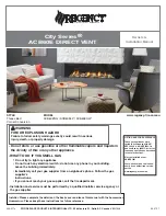
City Series ACB60E
|
3
table of contents
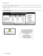
Copy of Safety Decal ........................................................................... 4
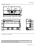
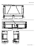
Dimensions - Bay Install ...................................................................... 5
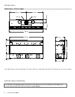
Dimensions - Corner Install ................................................................. 6
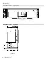
Gas Connection - Back of Unit ............................................................ 7
Gas Connection - Bottom of Unit ......................................................... 7
Gas Connection - Side of Unit ............................................................. 7
Electrical Connection - Bottom of Unit ................................................. 8
Electrical Connection - Side of Unit ..................................................... 8
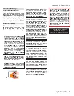
Important Message ............................................................................ 9
Before You Start ................................................................................... 9
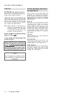
First Fire ............................................................................................ 10
Normal Operating Sounds Of Gas Appliances .................................. 10
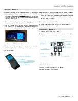
Lighting Procedure ............................................................................ 11
Shutdown Procedure ......................................................................... 11
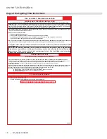
Copy of the Lighting Plate Instructions .............................................. 12
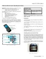
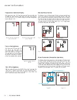
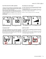
Proflame II Remote Control Operating Instructions ........................... 13
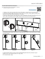
Front & Side Glass Barrier Removal .................................................. 17
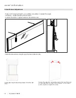
Glass Barrier Adjustment................................................................... 18
Inner Glass Panel Installation / Removal ........................................... 19
Inner Glass Panel (Firebox Glass) Installation / Removal
- Side Glass ..................................................................................... 21
Optional Front Barrier Glass Stoppers Installation / Removal ........... 22
Bulb Replacement ............................................................................. 23
Maintenance Instructions................................................................... 24
Log Replacement .............................................................................. 24
Glass ................................................................................................. 24
Glass Replacement ........................................................................... 24
General Safety Information ................................................................ 25
Installation Checklist .......................................................................... 25
Heatwave Duct System - Optional Kit ............................................... 25
Locating Your Gas Fireplace - Bay Install .......................................... 26
Locating Your Gas Fireplace - Corner Install ..................................... 26
Unit Assembly Prior to Installation ..................................................... 27
Clearances (3-sided) ........................................................................ 29
Clearances ........................................................................................ 30
Clearances - Corner Install ................................................................ 31
Mantel Clearances ............................................................................. 32
Mantel Leg Clearances ...................................................................... 32
305 mm .............................................................................................. 32
Framing Dimensions - Bay Install ...................................................... 33
Framing Dimensions Corner Kit - Corner Install (Right Corner) ........ 34
Framing Dimensions Corner Kit - Corner Install (Left Corner) .......... 35
Corner Installation Kit (Black) - Assembly Steps ............................... 36
Optional Framing Kit .......................................................................... 39
Chase Vent Installation (White Front) ................................................ 42
Wall Board/Plasterboard Installation.................................................. 43
No Screw Zones ................................................................................ 43
Framing and Finishing Inset Installations .......................................... 44
Typical Installations ............................................................................ 45
Typical Installations ............................................................................ 46
Flush TV with Hearth ......................................................................... 46
Finishing ............................................................................................ 47
Chase Venting ................................................................................... 48
Wall Mount On / Off Switch and Battery Holder Installation .............. 49
Exterior Flue Termination Locations .................................................. 50
Clearances ........................................................................................ 51
127 mm x 203 mm Rigid Pipe - Cross Reference Chart only ........... 52
Vent Restrictor Position ..................................................................... 54
Venting Introduction ........................................................................... 55
Venting Arrangement for Horizontal Terminations ............................. 55
Horizontal Terminations - Flex Vent 127 mm x 203 mm .................... 56
Horizontal Terminations - Rigid Pipe 127 mm x 203 mm ................... 57
Horizontal Terminations - Rigid Pipe 127 mm x 203 mm .................. 58
Horizontal Venting with Two 90
o
Elbows .......................................... 58
Horizontal Venting with Three 90
o
Elbows ....................................... 58
Vertical Terminations - Rigid/Flex Pipe 127 mm x 203 mm ............... 59
Vertical Terminations - Rigid/Flex Pipe 127 mm x 203 mm ............... 60
Venting Arrangement for Vertical Terminations With Straight
Vertical Venting and/or With a Max. of Two 90
o
Elbows
(1 - 90
o =
2 - 45
o
) .............................................................................. 61
Vertical Termination - 127 mmx 203 mm Flueing - Vertical Flex Kit
(Part 946-772) ................................................................................. 62
Vertical Termination - 127 mmx 203 mm Flueing - Vertical Flex Kit
(Part 946-772) ................................................................................. 63
Vertical Flue Extension Kit (Approved Models) (Part # 946-769) ...... 64
Ceiling Firestop / Firestop Spacer (Part 946-770) ............................. 64
Direct Flue Zero Clearance Top Exit Vertical Flue Kit - Installation
Instructions ...................................................................................... 65
High Elevation .................................................................................... 66
Gas Line Installation .......................................................................... 66
Pilot Adjustment ................................................................................. 66
Gas Pipe Pressure Testing ................................................................ 66
885 S.I.T. Valve Description ............................................................... 66
Wiring Diagram .................................................................................. 67
Glass Barrier Installation ................................................................... 68
Glass Barrier Adjustment................................................................... 69
Propane / ULPG Conversion Instructions .......................................... 70
Optional Fan Ducting Kit Installation .................................................. 72
Inner Black Panel Installation ............................................................ 75
Inner Enamel Panel Installation ......................................................... 77
Burner and Firebox Media Options .................................................... 79
Optional Driftwood Log Set Installation ............................................. 80
Optional Split Wood Log Set Installation ........................................... 83
Optional Birch Wood Log Set Installation .......................................... 86
Maintenance Instructions................................................................... 89
Log Replacement .............................................................................. 89
Glass Gasket ..................................................................................... 89
Glass ................................................................................................. 89
Glass Replacement ........................................................................... 89
Flame Pattern .................................................................................... 89
Valve Replacement ............................................................................ 90
Gas Maintenance .............................................................................. 91
Main Assembly .................................................................................. 92
Accessories ....................................................................................... 94
Warranty ........................................................................................... 96
Installer's information
Owner's information
Installation
Maintenance
Parts List
Summary of Contents for City ACB60E
Page 95: ...City Series ACB60E 95 notes ...
Page 102: ...102 City Series ACB60E notes ...
Page 103: ...City Series ACB60E 103 notes ...

