City Series ACB60E
|
65
installation
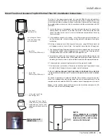
Direct Flue Zero Clearance Top Exit Vertical Flue Kit - Installation Instructions
This flue kit has been manufactured for use with ACB60E and to be installed in
accordance with AS/NZS 5601. To ensure safety and correct unit operation this flue
kit must be installed as outlined in these instructions. Heater and flue clearances
from combustible materials must be in accordance with these instructions and AS/
NZS 5601.
1. Locate the heater in its proposed position and mark the point for penetration
directly above the centre of the heater flue outlet. Check the heater location
allows the outer flue to clear all structural timber and combustible surfaces by
40mm minimum.
2. If the enclosure consists of a ceiling – cut a 303mm square hole (minimum) for
the flue to penetrate, cut hole through roofing material and prepare flashing for
termination.
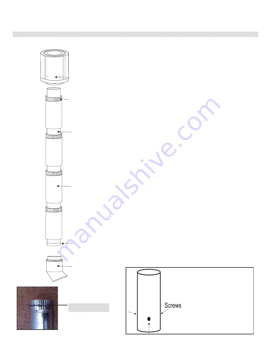
3. Starting at the heater, install first length of inner pipe, using Mill-Pac sealant and
self-tapping screws (or rivets). Note – first length of inner pipe has a Swage only.
4. Continue assembling flue pipes inner and outer, ensuring each inner join is sealed
using Mill-Pac sealant and self-tapping screws (or rivets). Outer flue pipe installs
crimped end up and must be sealed and fixed together also.
5. If required, fix outer flue in the ceiling space using non-combustible bracing to stop
movement. On penetration of roof, fit an appropriate flashing or weather seal to suit
the roofing material, ensure all joints outside are sealed with appropriate sealer.
6. Fit approved gas cowl ensuring inner and outer flue pipes are sealed.
7. Start heater and run for at least 15 minutes to check flue seal. If operational issues
are noted, check flue again to ensure proper seal of inner pipe.
SUPPLIED
Mill-Pac SEALANT MUST BE USED OR WARRANTY WILL BE VOID
– IF REQUIRED, MORE SEALANT CAN BE PURCHASED USING PART NUMBER
948-128
45º bends (if required) part number 946-688 – Note, if bends are used at the start
of flue run, a deeper crimp may be required at the unit for inner pipe fitment. Can be
crimped on site and sealed with Mill-Pac sealant and self- tapping screws (or rivets).
Note
– It is the installers responsibility to ensure the installation complies with AS/
NZS 5601 and all local and building codes.
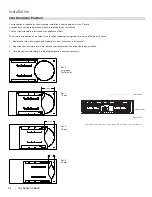
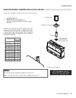
Gas Cowl
58DVA-VCH
Outer Flue
203mm dia x 900mm x 4
Inner flue
127mm dia x 900mm x 4
Outer Flue
203mm dia x 900mm x 4
Inner flue
127mm dia x 900mm x 4
Flomet Cap
If required 45° Inner Flue &
Outer Flue may be installed.
Install with pop rivets or self
tapping screws and seal with
Milpac
If required 45° Inner Flue &
Outer Flue may be installed.
Install with pop rivets or self
tapping screws and seal with
Milpac
1st Length Inner Flue
has Swage Only
1st Length Inner Flue
has Swage Only
Last Length of Outer
Flue has deep crimp
and is marked
Last Length of Outer
Flue has deep crimp
and is marked
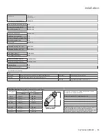
NOTE:
USE A MINIMUM OF 3 SCREWS
EQUIDISTANT TO SECURE EVERY
INNER FLUE PIPE JOINT AS WELL
AS MILL-PAC SEALANT
Mill-Pac SEALANT
INNER FLUE
Summary of Contents for City ACB60E
Page 95: ...City Series ACB60E 95 notes ...
Page 102: ...102 City Series ACB60E notes ...
Page 103: ...City Series ACB60E 103 notes ...

