City Series ACB60E
|
73
installation
2
920-347
11.05.20
ACB40E/ACC40LE/ACC40RE/ACV40AC/ACB60E/ACV60E
OPTIONAL FAN KIT INSTALLATION
NOTE:
Installation of Fan Kit should be done prior to
installation of the wall.
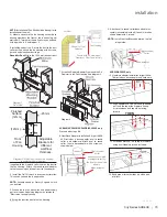
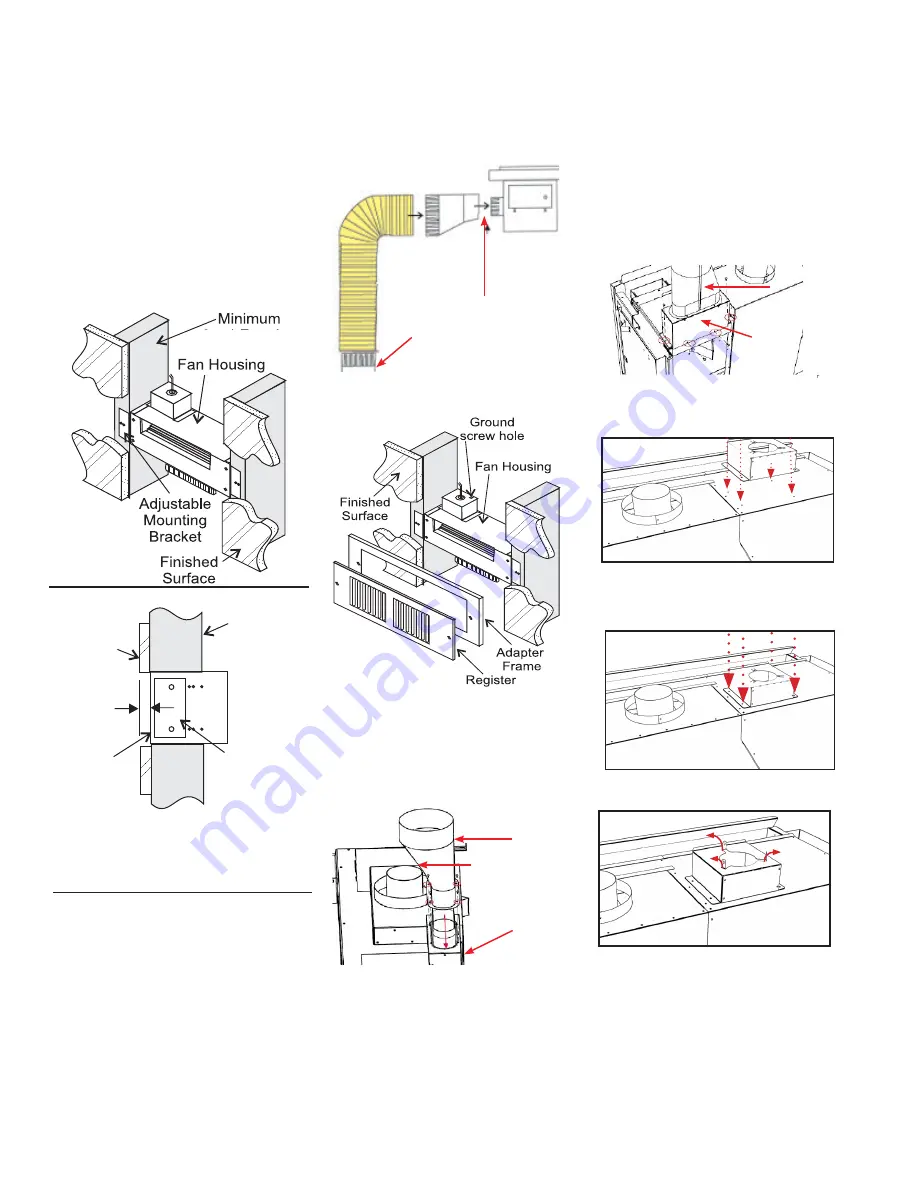
2) Mount and secure the fan housing assembly to
framing members, the front of the fan housing will
protrude 12.7mm out of the wall so it may be finished
with drywall, etc. See diagram 2
3. Install the air duct run. Secure the duct to the duct
collar on the unit and the fan housing with 3 screws
per end and aluminum duct tape.
Round Air Duct:
Attach the 152.4mm round air duct
Diagram 2: Side View - Secure fan housing
to minimum 45mm framing.
Diagram 1:
Front View
(supplied) to the fireplace collar and run the duct to
the fan housing. Attach the round-to-oval adapter
to the fan housing and the air duct to the adapter
45mm
Round to Oval
Adapter
Fan Housing
Secure with 3 Screws and
Aluminum Duct Tape at Unit
Air Duct
7. Screw the Register Adapter Frame and the Air
Register to the Fan Housing. See diagram 4.
Diagram 4
4. Install the On/Off switch in a convenient location.
This switch controls the fan operation.
NOTE:
Variable speed or Rotary 3 speed switch
can be fitted.
5. Wire up the the fan, wall switch and power supply
per local codes. See wiring diagram as reference.
*Electrician to supply wiring.
6. Screw fan junction box to the fan housing.
45mm
Finished
Surface
(12mm)
Front
of Fan
Housing
Adjustable
Brackets for
different
wall/floor
thickness.
(12mm)
8. HeatWave Adapter Installation Kit (part #656-
995) includes a base adapter, oval to round
collar, and hardware. Attach oval to round
collar, then to base adapter with 4 screws as
shown below.
9. Attach oval to round collar/base adapter as-
sembly (assembled in step 8) to unit in location
shown below with 4 screws.
NOTE:
Install the HeatWave adapter on the left
of right side.
Oval to round
collar
Ensure curved part
of adapter is facing
the front of the unit as
shown
Base adapter
Oval to round
collar
Base adapter
ACB40E/ACC40LE/ACC40RE/ACV40AC only
Proceed with steps 8-9.
11. Align adapter 946-766 so the hole pattern
on it and the top of the fireplace line up.
Air intake/open end should be facing
forward.
12. Screw adapter 946-766 to top of fireplace
using 4 self-tapping screws included.
THEN
10. Heatwave adapter installation kit (part # 946-
766) includes a base adapter and hardware.
ACB60E/ACV60E only
13. Bend pipe attachment tabs up with a pair
of pliers.
Summary of Contents for City ACB60E
Page 95: ...City Series ACB60E 95 notes ...
Page 102: ...102 City Series ACB60E notes ...
Page 103: ...City Series ACB60E 103 notes ...

