background image

Regency Freestanding Woodstove

10

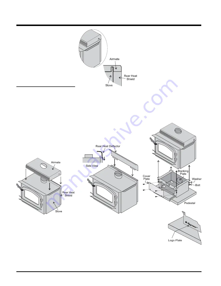
Diagram  4

Diagram 2

Diagram 3

STOVE ASSEMBLY 

PRIOR TO 

INSTALLATION

All units require either the pedestal or 4 legs at-
tached to the base. The F1100 and F3100 stoves 
require either the Airmate or Rear Heat Defl ector 
on top of the stove. Clearances to combustible 
materials vary depending on whether the airmate 
or rear heat defl ector is installed, so be sure to 
check the Minimum Clearance to Combustible 
Materials section.

Airmate Assembly

for F1100 & F3100


Small 850-105

 Large 

850-305

1)

  The airmate sits on top of the stove with 

the slots in the sides fi tting over the curved 
defl ector on the rear stove top. See diagram 
1. Discard the Rear Heat Defl ector that is 
supplied with the unit, it is not required if the 
airmate is installed. 

2)

  Center the airmate and push it forward to the 

front of the stove. The back of the airmate 
should be level with the back and sides of 
the rear heat shield. See Diagrams 2 & 3.

Diagram 1

Rear Heat Defl ector Assembly

for F1100 & F3100


Small 815-555

 Large 

815-556

The rear heat defl ector is supplied with the stove 
and must be installed unless the optional airmate 
has been selected. It stops the heat radiated from 
the fl ue collar from overheating the rear wall. The 
rear heat defl ector is installed on top of the rear 
heat shield, as shown in Diagram 4.

Pedestal Assembly


Small 850-115

 Large 

850-315

1)

  For easier assembly, tip the stove on its 

back (onto a soft surface to prevent scratch-
ing).


Hint:

 If you have chosen the Ash Drawer 

option, remove the ash dump cover plates 
before attaching the pedestal (refer to the 
Ashdrawer Kit Installation section).

2)

  Remove the blanking plate if: 

 a)

   you are 

not

 installing outside combustion 

air or 

 b) 

outside air is to be brought in from the 

rear

 of the stove.

3)

  Unscrew the 4 bolts in the under-side of the 

stove. Align the holes in the corners of the 
pedestal top with the corresponding holes 
in the base of the stove. Fasten using a bolt 
and washer for each corner.

4)

  Push the Regency logo 

into the two holes in 
the front bottom 
left corner of 
the pedestal 
cover plate.


Note:  Any paint touch up should be done 

prior to placing logo on pedestal.

5) 

If not using ash drawer, then cover plate must 
be installed. If using ash drawer, then disregard 
cover plate.

INSTALLATION

Summary of Contents for Classic F1100

Page 1: ...4 908 288c MODELS F1100S F3100L Freestanding Woodstoves 11 12 09 Owners Installation Manual Tested by Installer Please complete the details on the back cover and leave this manual with the homeowner Homeowner Please keep these instructions for future reference www regency fire com ...

Page 2: ...ALER in your area Keep those REGENCY FIRES burning SAFETY NOTES If this woodstove is not properly installed a house fire may result For your safety follow the installation instructions contact local building or fire officials about restrictions and installation inspection requirements in your area This appliance needs fresh air for safe operation and must be installed with adequate combustion air ...

Page 3: ...nector Pass throughs 13 Recommended Heights For Woodstove Flue 14 Mobile Home Installation 14 Listed Components For Mobile Home Installation 15 Brick Flue Baffle Secondary Air Tube Installation 16 Brick Installation 17 Door Handle 17 Glass Installation 17 Optional Accessories 17 Screen Door 17 OPERATING INSTRUCTIONS Operating Instructions 19 First Fire 19 Draft Control 19 Ash Disposal 20 Safety Gu...

Page 4: ...FROM HEATER REPLACE GLASS ONLY WITH NEOCERAM GLASS COMBUSTIBLE FLOOR MUST BE PROTECTED BY NON COMBUSTIBLE MATERIAL EXTENDING BENEATH THE HEATER AND TO THE FRONT AND SIDES AS INDICATED OR TO THE NEAREST PERMITTED COMBUSTIBLE MATERIAL OPTIONAL COMPONENT FAN ELECTRICAL RATING VOLTS 115 60 HZ 2 AMPS SCREEN DOOR MINIMUM CLEARANCES TO COMBUSTIBLE MATERIALS F1100S WITH AIRMATE SHIELD F1100S WITHOUT AIRMA...

Page 5: ...H DOOR CLOSED OPEN FEED DOOR TO FEED FIRE ONLY DO NOT USE GRATE OR ELEVATE FIRE BUILD WOOD FIRE DIRECTLY ON HEARTH DO NOT OVERFIRE IF HEATER OR CHIMNEY CONNECTOR GLOWS YOU ARE OVERFIRING INSPECT AND CLEAN CHIMNEY AND CONNECTOR FREQUENTLY UNDER CERTAIN CONDITIONS OF USE CREOSOTE BUILDUP MAY OCCUR RAPIDLY KEEP FURNISHINGS AND OTHER COMBUSTIBLE MATERIAL AWAY FROM HEATER REPLACE GLASS ONLY WITH NEOCER...

Page 6: ...Regency Freestanding Woodstove 6 UNIT DIMENSIONS F1100S Dimensions F3100L Dimensions 25 1 4 641mm DIMENSIONS ...

Page 7: ...is unit to a chimney serving another appliance unless approved by your local building authority 12 A chimney connector cannot pass through an attic or roof space closet or similar concealed space or a floor ceiling wall or partition of combustible construction In Canada if pas sage through a wall or partition of combustible construction is desired the installation shall conform to CAN CSA B365 Ins...

Page 8: ...2 16 23 5 with Rear Deflector 20 12 10 34 18 5 23 5 NOTE Be aware that local Codes and Regulations may override some clearances listed in this manual Check with your local inspector Residential Installation C Vent Single Wall Unit From Unit From Corner From Flue Center line A B C D E F Small F1100S with Airmate 13 11 8 25 17 5 20 with Rear Deflector 15 10 5 11 27 17 23 Large F3100L with Airmate 18...

Page 9: ...efined by local codes extend ing beneath the heater and a minimum of 6 from each side and minimum 16 from the front face of the stove and minimum 6 or the rear clearance to combustibles whichever is smaller from the rear of the stove NOTE In Canada floor protection must extend 18 to the front and 8 to each side of the stove From From Flue Min Min Hearth Unit Unit Center line Width to Rear Wall G H...

Page 10: ...6 Therearheatdeflectorissuppliedwiththestove andmustbeinstalledunlesstheoptionalairmate hasbeenselected Itstopstheheatradiatedfrom thefluecollarfromoverheatingtherearwall The rear heat deflector is installed on top of the rear heat shield as shown in Diagram 4 Pedestal Assembly Small 850 115 Large 850 315 1 For easier assembly tip the stove on its back onto a soft surface to prevent scratch ing Hi...

Page 11: ...decrease problems such as difficult start ups back smokingwhendoorisopen and dirty glass It might be sufficient to initiallytrywiththeminimumrequired height and then if problems do arise add additional height at a later date 4 Slide the roof flashing over your chimney and seal the flashing to the roof with roofing compound Secure the flashing to your roof with nails or screws 5 Place the storm col...

Page 12: ...re no cracks loose mortar or other signs of deterioration and blockage Have the chimney cleaned before the stove is installed and operated When connecting the stove through a combustible wall to a masonry chimney special methods are needed Ensure that an effective vapour barrier at the location where the chimney or other component penetrates to the exterior of the structure MASONRY FIREPLACE There...

Page 13: ...rick and combustibles 2 in 50 8mm Minimum clearance 12 in 304 8mm of brick Chimney connector Fire clay liner Method C 6 152 4 mm Clearance to Combustible Wall Member Starting with a minimum 24 gage 024 61 mm 6 152 4 mm metal chimney connector and a minimum 24 gage ventilated wall thimble which has two air channels of 1 25 4 mm each construct a wall pass through Thereshallbeaminimum6 152 4 mmsepara...

Page 14: ... Example b One 90 deg elbow 2 ft 2 ft of horizontal run 4 ft one T 3 ft Total Addition at sea level 9 ft Recommended Flue Height Elevation Example a Example b 0 18 21 1000 18 72 21 84 2000 19 44 22 68 5000 21 60 25 20 8000 23 76 27 72 Once you have properly marked the position of your unit and the floor protection as outlined in the Residential Installation items 1 through 8 a supply of fresh air ...

Page 15: ...ll and Large Freestanding pedestal units are approved for installation in a Mobile Home if one of the following pipe systems is used U S Installation METALBESTOS SSII Qty Part Description 1 6DS VK Connector Kit 1 6TMH Shield Support 1 6TAF 6 Flashing 1 6T 36 Chimney Length 1 6T 18 Chimney Length 1 6T CT Rain Cap PRO JET 3103 Qty Part Description 1 PV06 TK Connector 1 CSB Shield Support 1 RRS Radia...

Page 16: ...y occur if the bafflesareimproperlypositioned Checkthe position of the brick baffles on a regular basis as they can be dislodged if too much fuel is forced into the firebox The Large Stoves F3100L and S3100L are shipped with one of the secondary air tubes loose inside the firebox It needs to be installed after the brick baffle are installed Follow the directions below Small Stove F1100S 1 If the t...

Page 17: ...rebox and replace all the bricks except for the brick over the ash plug See brick diagrams 5 Place the ash plug tool beside the lid then slide the ash drawer inside Refer to the Ash Drawer Operating section Freestanding Small F1100 Pedestal Ash Drawer Kit 850 100 1 Remove the bricks from the floor of the firebox 2 If using ashdrawer discard cover plate 3 Remove the ash dump cover plates one inside...

Page 18: ... Red Black Fan Thermodisc normally open 120V AC 60 Hz Blower Fan Wiring Diagram CAUTION Label all wires prior to disconnection whenservicingcontrols Wiringerrorscancause improper and dangerous operation WARNING Electrical Grounding Instructions This appliance is equipped with a three pronged grounding plug for your protection against shock hazard and should be plugged directly into a properly grou...

Page 19: ...nent dam age to the unit and void your warranty FIRST FIRE When your installation is completed and in spected you are ready for your first fire 1 Open control fully 2 Open firebox door and build a small fire using paper and dry kindling Secure door on the firebox and wait a few minutes for a 13 Allfuelburningappliancesconsumeoxygen during operation It is important that you supply a source of fresh...

Page 20: ...eep the door closed during operation and maintain all seals in good condition 3 Do not burn any quantities of paper gar bage and never burn flammable fluids such as gasoline naptha or engine oil in your stove 4 Ifyouhavesmokedetectors preventsmoke spillage as this may set off a false alarm 5 Do not overfire heater If the chimney con nector flue baffle or the stove top begin to glow youareoverfirin...

Page 21: ...losertothedoorframe causingatighter seal Removeandreplacethenuts washerand spacer as shown GLASS MAINTENANCE Your Regency stove is supplied with 5 mm Neoceram ceramic glass that will withstand the highest heat that your unit will produce In the event that you break your glass by impact purchase your replacement from an authorized Regencydealeronly andfollowourstep by step instructions for replacem...

Page 22: ...r Gasket Repair Kit 17 846 918 Hinge Cap Gold 2 set 948 079 Hinge Cap Nickel each 19 948 101 Spring Handle Large Gold 948 135 Spring Handle Large Nickel 20 948 102 Spring Handle Small Gold 948 136 Spring Handle Small Nickel F1100 F3100 STOVE MAIN ASSEMBLY Part Description Part Description 846 515 Complete Fan Blower Assy 120 V 25 910 684 Power Cord 120 V 27 910 142 Thermodisc Fan AutoON OFF 28 910...

Page 23: ...Plug Tool Handle 56 850 121 Bottom Shield Small 850 321 Bottom Shield Large 57 Blanking Plate Btm Shield 850 101 Ashdrawer Kit Btm Shield 55 Ashdrawer Bottom Shield 58 942 110 Ash Plug 59 820 249 Ash Plug Tool Handle 140 850 126 Legs Cast Black 850 127 Legs Cast Gold 850 128 Legs Cast Brush Nickel 948 216 Regency Logo Gold 948 223 Regency Logo Nickel Not available as a replacement part PEDESTAL BO...

Page 24: ...Partial 1 1 4 x 4 1 2 x 3 1 2 76 Brick Partial 1 1 4 x 2 x 9 77 Brick Partial 1 1 4 x 3 1 4 x 9 78 Brick Partial 1 1 4 x 4 1 2 x 3 1 4 79 Brick Partial 1 1 4 x 4 1 2 x 2 1 4 80 Brick Partial 1 1 4 x 6 1 2 x 2 1 4 81 Brick Partial 1 1 4 x 1 1 4 x 9 82 Brick Partial 1 1 4 x 3 1 8 x 4 1 2 83 Brick Partial 1 1 4 x 3 3 8 x 9 84 Brick Partial 1 1 4 x 4 1 2 x 8 85 Brick Partial 1 1 4 x 4 1 4 x 8 Not avai...

Page 25: ...Regency Freestanding Woodstove 25 NOTES ...

Page 26: ...Regency Freestanding Woodstove 26 NOTES ...

Page 27: ...costs of workmanship from unauthorized service persons or dealers At all times FPI reserves the right to inspect product in the field which is claimed to be defective All claims must be submitted to FPI by authorized selling dealers It is essential that all submitted claims provide all of the necessary information including customer name purchase date serial type of unit problem and part or parts ...

Page 28: ...__________________________________________________ Printed in Canada Regency fireplace products are designed with reliability and simplicity in mind In ad dition ourinternalQualityAssuranceTeam carefully inspects each unit thoroughly before it leaves our door Fireplace Products International Ltd is pleased to extend this Limited Lifetime Warranty to the original pur chaser of a Regency Product See...

Reviews: