background image

8

Regency CS2400  Freestanding Wood Stove

INSTALLATION

Z

6"

6"

16"

Y

Y

X

X

6"

for

angled

corners

6"

16"

6"

6"

Z

Fuel Door
Opening

The Regency Freestanding models have been alcove approved and must be installed 
with a listed double wall connector to the ceiling level. 

Note:  Minimum alcove ceiling height - 84"


Maximum depth of alcove - 36"

    Minimum Overall Width (X) of Floor 
       Protector


for all installations: 

 US 

38-3/8"


 Canada 

42-3/8"

Floor Protection

A combustible 

fl

 oor must be protected by a non-combustible material (like tile, 

concrete board, or certi

fi

 ed to UL-1618 or as de

fi

 ned by local codes) extending 

beneath the heater and a minimum of 6" from each side and minimum 16" from 
the

 fuel door opening

 of the stove and minimum 6" (or the rear clearance to 

combustibles whichever is smaller) from the rear of the stove. 

NOTE: In Canada, fl oor protection must extend 18" to the front and 8" to 

each side of the stove.

Minimum Alcove Clearance to Combustible Materials

Unit

From Back Shield

+ Side Shields.

From Flue

Center-Line

Min.

Width

Min. Hearth
to Rear Wall

CS2400

G

H

I

J

K

L

15"

6.5"

28"

14-7/8"

56"

47-1/2"

Minimum Overall Depth (Y) of Floor Protector

Unit

Residential

"C" Vent

Residential

Close Clearance

Mobile Home

Close Clearance

Alcove

CS2400

Y

Z

Y

Z

Y

Z

Y

Z

USA

47-5/16"

6"

47-5/16"

6"

47-5/16"

6"

47-5/16"

6"

Canada

51-5/16"

8"

51-5/16"

8"

51-5/16"

8"

51-5/16"

8"

MINIMUM ALCOVE CLEARANCE TO COMBUSTIBLE MATERIALS

MEASUREMENTS "FROM UNIT" ARE FROM THE SIDE SHIELDS OF THE STOVE TO A SIDE WALL OR TO A CORNER, AND 

FROM THE REAR HEAT SHIELD TO A BACK WALL

Note:


If venting horizontally, fl oor protection must extend under the chimney connector and 2" inches beyond each side.

Summary of Contents for CS2400

Page 1: ...Canada V4G 1H4 918 926a CS2400 Alterra Freestanding Wood Stove 02 15 12 Owner s Installation Manual Tested by Installer Please complete the details on the back cover and leave this manual with the homeowner Homeowner Please keep these instructions for future reference ...

Page 2: ...Y DEALER in your area Keep those REGENCY FIRES burning SAFETY NOTES If this wood stove is not properly installed a house fire may result For your safety follow the installation instructions contact local building or fire officials about restrictions and installation inspection requirements in your area This appliance needs fresh air for safe operation and must be installed with adequate combustion...

Page 3: ...TEUR EN CERTAINES CONDITIONS D UTILISATION UN DÉPÔT DE CRÉOSOTE PEUT SE FORMER RAPIDEMENT GARDEZ LES MEUBLES ET AUTRES MATÉRIAUX COMBUSTIBLES ÉLOIGNÉS DU POÊLE REMPLACEZ LA VITRE SEULEMENT PAR DU VERRE EN NEOCERAM LE PLANCHER COMBUSTIBLE DOIT ÊTRE PROTÉGÉ PAR DES MATÉRIAUX NON COMBUSTIBLES DÉPASSANT DU DESSOUS DU DEVANT ET DES CÔTÉS DU POÊLE TEL QU INDIQUÉ OU JUSQU AU MATÉRIAU COMBUSTIBLE LE PLUS ...

Page 4: ... 14 Listed Components For Mobile Home Installation 14 Stainless steel smoke deflector Installation 15 Flue Baffle Secondary Air Tube Installation 16 Brick Installation 16 Door Handle 16 Side panel Installation 17 Ash drawer option 18 Lower Surround door reversal 19 Cast Door reversal 20 Wood Storage 21 Ashlip Installation 21 Optional outdoor Air kit installation 22 Blower Fan installation 23 Fan O...

Page 5: ...tove 5 DIMENSIONS UNIT DIMENSIONS 17 3 16 39 1 8 41 1 8 25 15 16 44 7 8 23 3 8 28 7 8 21 1 2 26 3 8 26 5 16 26 5 16 8 5 16 17 1 8 CL for outside air 27 5 16 to rear shield to optional fan Shown with optional fan installed 6 flue collar ...

Page 6: ...be connected to any air distribution duct INSTALLATION CHECKLIST 1 Locate appliance a Refer to Residential Installation section b Clearances to Combustibles Refer to Clearances section c Alcove Clearance Refer to Alcove Clearance section d ChimneyRequirements Referto Masonry Chimney Factory Built Chimney Combustible Wall Chimney Connector Pass Throughs section 2 Minimum Flue Height Refer to Minimu...

Page 7: ...line CS2400 A B C D E F 18 12 6 5 31 20 3 8 19 3 16 Residential Close Clearance To be installed with required pipe components When the stove is installed as a close clearance residential unit a listed double wall connector is required from the stove collar to the ceiling level From Unit From Corner From Flue Center line CS2400 A B C D E F 15 6 5 6 28 14 7 8 18 11 16 Mobile Home Close Clearance To ...

Page 8: ...r the rear clearance to combustibles whichever is smaller from the rear of the stove NOTE In Canada floor protection must extend 18 to the front and 8 to each side of the stove Minimum Alcove Clearance to Combustible Materials Unit From Back Shield Side Shields From Flue Center Line Min Width Min Hearth to Rear Wall CS2400 G H I J K L 15 6 5 28 14 7 8 56 47 1 2 Minimum Overall Depth Y of Floor Pro...

Page 9: ...t is recommended that no ceiling support member be cut for chimney and support box installation If it is necessary to cut them the members must be made structurally sound 2 Install radiant shield and support from above 3 Stacktheinsulatedpipeontoyourfinishsupport to a minimum height of 3 feet above the roof penetration or 2 feet above any point within 10 feet measured horizontally There must be at...

Page 10: ... inspected by a professional Make sure there are no cracks loose mortar or other signs of deterioration and blockage Have the chimney cleaned beforethestoveisinstalledandoperated Whenconnect ing the stove through a combustible wall to a masonry chimney special methods are needed Ensure that an effective vapour barrier at the location where the chimney or other component penetrates to the exterior ...

Page 11: ...clearance to brick and combustibles 2 in 50 8mm Minimum clearance 12 in 304 8mm of brick Chimney connector Fire clay liner Method C 6 152 4 mm Clearance to Combustible Wall Member Starting with a minimum 24 gage 024 61 mm 6 152 4 mm metal chimney connector and a minimum 24 gage ventilated wall thimble which has two air channels of 1 25 4 mm each construct a wall pass through There shall be a minim...

Page 12: ...00 16 0 17 0 18 5 20 0 24 0 21 0 26 5 9000 10000 16 5 17 5 19 0 20 5 24 5 22 0 27 0 NOTE No more than two offsets four elbows allowed Two 45o elbows equal one 90o elbow RECOMMENDED HEIGHTS FOR WOODSTOVE FLUE Simple rules on draft See Table 1 1 At sea level minimum height is 12 straight 2 Addthefollowingverticalheighttocompensate for 45 deg elbow 1 ft 90 deg elbow 2 ft T 3 ft Each foot of horizonta...

Page 13: ... Use 4 duct pipe with a mesh grill to pipe fresh air into the back shield area Place your unit in position and secure it to the floor using two lag bolts 3 8 x 3 1 2 through the two holes inside the pedestal base See page 9 for installation instructions For Mobile Home units installed in the U S the unit must be grounded using a 8 ground wire with approved termination and star washer Secured to fl...

Page 14: ...ion 1 DL42A 6 Connector Kit 1 6XSF Support 1 6XFA Flashing 1 6XL3 Chimney Length 1 6XL18 Chimney Length 1 6XCPE Rain Cap METAL FAB TEMP GUARD 2100 Qty Part Description 1 6DWBK Connector 1 6TGRS Roof Support 1 6TGG36 Chimney Length 1 6TGG12 Chimney Length 1 6TGF Flashing 1 6TGC Rain Cap AMERI TEC HS Qty Part Description 1 6DCC Connector 1 6HSRS 12 Roof Support 6PLRS 12 BK 1 6F Flashing 1 6HS 36 Chi...

Page 15: ...out Install new defector and hand tighten bolts Ensure positive location of the defector prior to hand tightening WARNING Operation of the unit with out proper installation of smoke deflector will void warranty Smoke deflector installed with 2 bolts Note This is a view from the back of the unit through the top Smoke deflector is installed through the door opening in location shown in diagram Ensur...

Page 16: ...ue on to Step 2 if not follow the instructions below Install the air tube into the holes in the side channels The notch goes on the right hand side with the air holes facing toward the door Slide the tube into the left hand side as far as possible and then bring it back into the hole on the right hand side until it locks into position If the tube will not slide in easily simply use a pair of vise ...

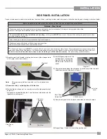
Page 17: ...t to the unit Failure to do this will result in burn stains on panels which you will be unable to remove Not protected by product warranty One set of side panels needs to be installed on the stove When installing stainless steel side panels follow the handling and cleaning instructions below 1 Bend the metal tab located in the top front corner of the side panels to a 45 angle with a pair of pliers...

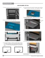
Page 18: ...al in operating instructions 1 Open the main top door and the center door on the front of the unit 3 Remove the ash dump cover plates one inside the firebox and one on the underside of the firebox access the lower plate through the center door it is directly below the upper ash dump plate by removing the two nuts and bolts holding the 2 plates together from underneath the stove Ash Dump Plates Ash...

Page 19: ...tained within the manual package Rotate the hinge 180 and reinstall on the right side 4 Rotate both hinge and latch 180 and reinstall hinge on left side latch on right side 5 Remove and rotate both the male part of the latch 180 located on the inside of the lower surround door Install the latch on the opposite side of the door Door latch male portion 6 Reinstall the door do not rotate onto the hin...

Page 20: ...curing the door catch assembly to the unit 6 Remove the glass from the door and flip it around 180 so the painted strip is at the bottom of the door 7 Flip the handle around 180 and reattach to the door with 2 botls 4 Flip the door hinge 180 install on the left side of the unit with 2 bolts 5 Reattach the door catch assembly on the right side with 2 bolts from step 3 Door Catch Door Catch Door Hin...

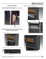
Page 21: ... within pedestal Note Please refer to local codes B365 NFPA211 and your local jurisdiction Store wood behind opening 1 Open lower surround door 2 Ashlip to be positioned just below the ashdrawer if installed 3 Manoeuvre ashlip into position on an angle the tabs on the ashlip rest behind side walls on unit see diagrams below Tabs on ashlip Final install of Ashlip Ashlip to be positioned here ...

Page 22: ...crews from locations shown below to remove backing plate 2 Center the plate pipe over the opening on the back of the stove Secure with 4 self tapping screws 3 Reinstall the backing plate over the air kit pipe Secure with 4 screws removed from step 1 4 Slide cap over end to pipe to complete the installation ...

Page 23: ...with a three pronged grounding plug for your protection against shock hazard and should be plugged directly into a properly groundedthree prongreceptacle Donotcutorremove the grounding prong from this plug NOTE This appliance when installed must be electrically grounded in accord ance with local codes or in the absence of local codes with the National Electrical Code ANSI NFPA 70 or the Canadian E...

Page 24: ...flamemaybedrawnout of the fireplace stove opening creat ing risks from both fire and smoke DRAFT CONTROL Both the primary and air wash drafts are controlled by the control rod located on the left side of the unit when facing the unit To increase your draft pull open and to decrease push closed All units have a secondary draft system that continually allows combustion air to the induction ports at ...

Page 25: ...hes out of the stove when the stove is cold Remove the plug by lifting on the handle using the tool provided Push the ashes down the hole into the ash drawer the large pieces can be left in the firebox and burned during the next fire or removed through the door opening 2 Always leave 1 2 to 1 inch of ash in the bottom of the firebox This helps in easier starting and a more uniform burn of your fir...

Page 26: ...thods for supporting fuel Burn directly on the bricks 11 Open the draft control fully for 10 to 15 seconds prior to slowly opening the door when refuelling the fire 12 Do not connect your unit to any air distribution duct 13 Your woodstove must burn dry seasoned standard firewood only The use of cut lumber plywood mill ends coal charcoal etc is prohibited as this fuel can easily over heat your woo...

Page 27: ... stove and remove the glass retainer Use caution when removing broken glass to avoid injury When placing the replacement glass in the door make sure that the glassgasketingwillproperlysealyourunit Replace the retainer it should rest on the gasket not the glass and tighten securely with a glass clips and screws Do not wrench down on the glass as this may cause breakage Do not use substitute materia...

Page 28: ...t Test the seal on the loading door with a paper bill Place a paper bill in the gasketed area of the door on a cold stove close the door Try to remove the paper by pulling The paper should not pull out easily if it does try adjusting the door latch if that doesn t solve the problem replace the door gasket Check and lubricate door hinge latch Use only high temperature anti seize lube ie never seize...

Page 29: ...nt Leg 6 076 011 Rear Fan Clip 7 200 917 Fan Assembly 8 146 003 Side Shield LH 9 146 002 Side Shield RH 10 146 514 Pedestal Assembly 11 156 523 Door Hinge Assembly 12 220 516 Ash Drawer Assembly 13 156 523 Door Catch Assembly 14 146 517 Heat Shield Assembly 15 146 517 Back Shield Assembly 16 146 512 Firebox Assembly 17 146 011 Top Bottom Vents 18 146 008 Side Support 19 948 216 Regency Logo plate ...

Page 30: ...ght Hand 5 200 228 Fan Bracket Left Hand 6 200 229 Fan Housing Back 7 910 157 P Fan 8 910 142 Thermodisc Part Description 1 020 960 Firebrick Set 2 033 953 Air Tube 3 4 Qty 4 3 020 957 Baffle set RED LOW WHITE COMMON CONNECTION DIAGRAM BLACK HIGH 115V 60HZ 1 1A J250 150 O44003 T P 3000 RPM JAKEL INC DATE T P L B 5 6 2 3 4 7 8 1 FAN ASSEMBLY FIRE BRICK AIR TUBE BAFFLE 3 1 2 ...

Page 31: ... or costs of workmanship from unauthorized service persons or dealers At all times FPI reserves the right to inspect product in the field which is claimed to be defective All claims must be submitted to FPI by authorized selling dealers It is essential that all submitted claims provide all of the necessary information including customer name purchase date serial type of unit problem and part or pa...

Page 32: ..._________________________________________ Serial No __________________________________________________________ Register your Regency warranty online www regency fire com Reasons to register your product online today View and modify a list of all your registered products Request automatic email notification of new product updates Stay informed about the current promotions events and special offers ...

Reviews: