30
|
Regency
®
E18 Gas Fireplace Insert
|
30
installation
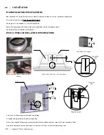
7 3/16"
183mm
6 1/16"
155mm
1 1/2"
39mm
A
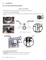
28-F / 28F-2 Firebox
B
28-F / 28F-2 Firebox
E18 Insert
DETAIL A
SCALE 1 : 4
Leg height setting
DETAIL B
SCALE 1 : 4
Adaptor Plate
fastener setting
2 5/8"
66mm
28-F & 28F-2 Installation Specifications
Leg Setting / Outer Shell Position
Flex Adaptor Length
Collar Plate Setting / Vent position
E18 INSTALL SPECIFICATIONS
See Installation of E18 into Existing Units for General Installation Guidance for Vent Configuration.
This install of the E18 uses V
ent Connection Type A.
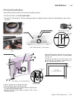
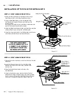
The Length of 4" Flex needed is 2-5/8" semi-expanded. Secure flue adapter top plate to under side of existing firebox using 4 self taping
screws.
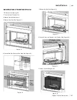
28 F / 28 F2 INSTALLATION SPECIFICATIONS
1
. Loosen 2 x philips screws on both right and left legs.
2
. See above diagram below for required leg setting.
3.
Install with supplied phillips screws to prepunched holes and tighten previous screws that were loos-
ened in Step 1.
4
. Keep left side leg loose until outer firebox is in position in ZC box - to allow adjustment of gas line.
Right side shown
Set to this
hole
Set to this
hole
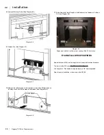
Secure top plate to firebox w/4 screws.
Secure vent slide plate to flex pipe with 4
screws
Summary of Contents for E18-LP
Page 1: ......
Page 74: ...Regency E18 Gas Fireplace Insert 73 73 notes ...
Page 75: ...74 Regency E18 Gas Fireplace Insert 74 notes ...

