46
|
Regency
®
E18 Gas Fireplace Insert
|
46
installation
919-284a
03/17/15
7a.
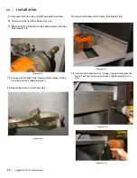
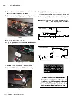
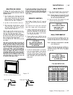
Basic or FireGenie remote : Attach the other black wire from the
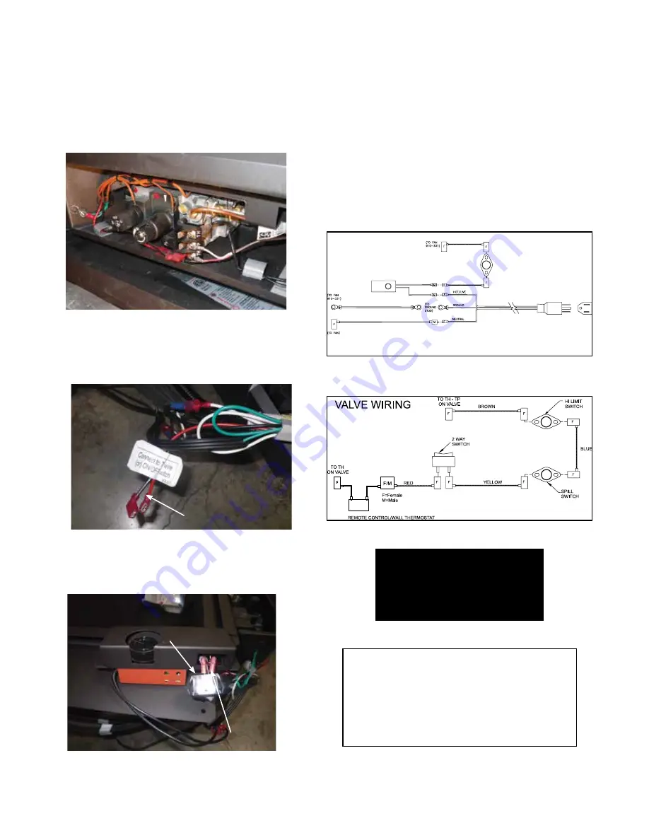
remote receiver to TH on the valve, see Diagram 7.
7b.
GT remote control: Attach the green wire from the wiring harness
labeled TH and attach wire to TH on the valve, see Diagram 7.
8. Tuck all wires neatly into base of the unit.
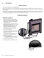
9. Locate the red and black ON/OFF switch wires from the appliance,
see Diagram 8.
10. Locate the ON/OFF switch, packed in the manual package.
11. Connect ON/OFF switch wires to ON/OFF switch, see Diagram 9.
12. Snap ON/OFF switch into position.
Note: Ensure when snapped into position—the empty
terminal on the back side of the switch is facing upward, see Diagram 9.
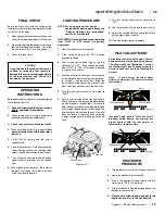
13. Code remote control. See remote control manual for coding instruc-
tions and battery installation.
Important Note: When remote control is coded, ensure that the ON/OFF
switch is in the on position or facing up and the remote
receiver is in the remote position.
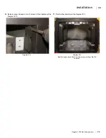
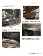
Diagram 7
Diagram 8
Diagram 9
WHITE
WHITE
GREEN
BLACK
ROTARY SPEED CONTROL
THERMODISC
CAUTION: Label all wires prior
to disconnection when servicing
controls. Wiring errors can
cause improper and dangerous
operation.
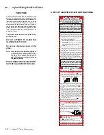
WARNING: Electrical Grounding Instructions
This appliance is equipped with a three pronged
(grounding) plug for your protection against shock
hazard and should be plugged directly into a prop-
erly grounded three-prong receptacle. Do not cut
or remove the grounding prong from this plug.
A N WIRING
Empty terminal
ON/OFF switch wires
ON/OFF switch wires
2
E18
Summary of Contents for E18-LP
Page 1: ......
Page 74: ...Regency E18 Gas Fireplace Insert 73 73 notes ...
Page 75: ...74 Regency E18 Gas Fireplace Insert 74 notes ...

