Regency
®
E18 Gas Fireplace Insert
|
57
57
|
installation
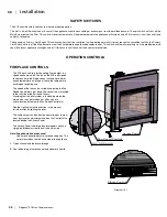
E18 Shown with front faceplate removed
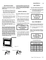
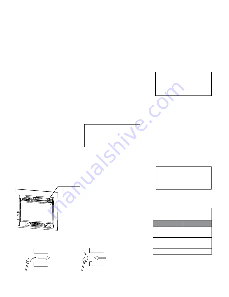
Drafthood Opening
Proper Draft
Improper Draft
Thermostat Wire Table
CAUTION
Do not wire millivolt
wall thermostat wires
to 120V wire.
CAUTION
Do not wire millivolt
wall thermostat wires
to 120V wire.
WALL SWITCH
1)
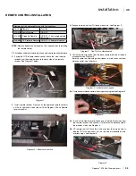
Run the wire through the right or left side inlet
opening. Be careful not to damage the wire.
Note: We recommend a maximum of 15' of wire
but if you wish to go with a longer run,
use the Thermostat Wire Table.
2)
Connect the wire to the supplied wall switch
and install into the receptacle box.
REMOTE CONTROL
Use the Regency Remote Control Kit approved
for this unit. Use of other systems may void your
warranty.
The remote control kit comes with a hand held
transmitter, a receiver and a wall mounting plate.
1.
Choose a convenient location on the wall to
install the receiver and the receptacle box (pro-
tection from extreme heat is very important).
Run wires from the fireplace to that location.
Use Thermostat Wire Table.
2.
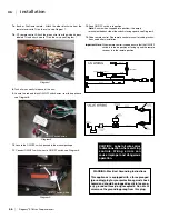
Disconnect the two wires, Red/Black from the
on/off switch. Connect the receiver wires to the
Red/Black wires only.
3.
Install 3 AAA alkaline batteries in transmitter
and 4 AA alkaline batteries in the receiver.
Install the receiver and its cover in the wall.
Switch the remote receiver to "remote" mode.
The remote control is now ready for operation.
Note: Transmitter and receiver need to be
programmed.
WALL THERMOSTAT
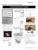
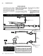
A basic wall thermostat is supplied with the unit,
connect the wires as per the wiring diagram. Use
table below to determine the maximum wire length.
Note: Preferable if the thermostat is installed
on an interior wall.
Regency offers an optional programmable thermo-
stat but any 250-750 millivolt rated non-anticipator
type thermostat that is CSA, ULC or UL approved
may be used.
DRAFTHOOD CHECK
A "spillage" test must be made before the in-
stalled unit is left with the customer. Follow the
procedure below:
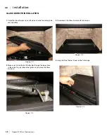
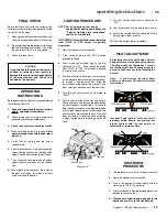
1.
Start all exhaust fans in the home and then
close all external doors and windows in the
house. Remove the Front Trim from the E18 to
gain better access to the Drafthood Opening.
Make sure the Glass Door is on properly.
2.
Light the unit and set controls to maximum.
3.
After five minutes, test that there is a “pull” on
the flue by placing a smoke match, cigarette or
similar device which gives off smoke, in front of
the spill tube. See diagram 14.1.
Check for proper draft by placing a match close
to the drafthood opening. This should be checked
after the unit has been operating for 15 min.
The smoke should be drawn into the Drafthood. If
the smoke is still not drawn into the Drafthood turn
the unit off and check for the cause of the lack of
draft. If necessary, seek expert advice.
For wind turbulent sites, a wind cap may remedy
the problem.
Note: The thermally activated safety switch will
sense the change in temperature and shut down
the gas valve in the event of a severe downdraft
or a blocked or disconnected vent. The switch
acts as a safety shut-off to prevent a build-up
of carbon monoxide. If the flue is blocked or
has no "draw", the switch will automatically
shut off the supply of gas within 5 - 10 minutes.
Tampering with the switch can result in carbon
monoxide (CO) poisoning and possible death.
If the heater turns off because of lack of draft
during the spillage test, check for the cause and
if necessary, seek expert advice.
The thermally actuated safety switch will auto-
matically reset after it has cooled off. The switch
will continue to cycle until the draft problem is
corrected. DO NOT BYPASS OR DISCONNECT
THIS SWITCH.
Diagram 14.1
Recommended Maximum Lead Length
(Two-Wire) When Using Wall
Thermostat (CP-2 System)
Wire Size
Max. Length
14 GA.
50 Ft.
16 GA.
32 Ft.
18 GA.
20 Ft.
20 GA.
12 Ft.
22 GA.
9 Ft.
CAUTION
Do not wire millivolt
wall switch wire
to 120V wire.
Summary of Contents for E18-LP
Page 1: ......
Page 74: ...Regency E18 Gas Fireplace Insert 73 73 notes ...
Page 75: ...74 Regency E18 Gas Fireplace Insert 74 notes ...


