background image


 Regency

®

 E18 Gas Fireplace Insert

  |     

63

63

maintenance

IMPORTANT

Disconnect power supply 

before servicing.

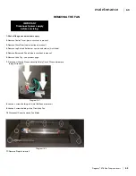
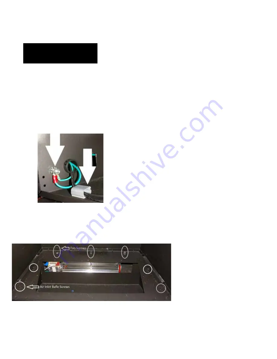
REMOVING THE FAN

1. 

Shut off the gas and electrical supply.

2. 

Remove Control Cover. (see instructions in manual)

3.

 Remove Glass Door.(see instructions in manual)

4.

 Remove Log Set and Embers or crystals and stones (if installed).

5.

 Remove Burner and Panels (see instructions in manual)

6.

 Remove Valve Tray - see previous page.

7.

    Disconnect Ground Wires and unclip Safety Circuit  Wires and remove 

through Grommet .

8.

 Loosen 4 screws holding in Air Inlet Baffle and remove it.

9. 

Loosen 3 screws holding in the Circulation Fan.

10

. Disconnect Power Leads on Fan Motor 

11. 

Reverse Steps to reinstall.

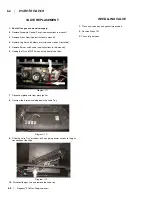
Diagram 18.1

Diagram 18.2

Summary of Contents for E18-LP

Page 1: ......

Page 2: ... vapors and liquids in the vicinity of this or any other appliance WHAT TO DO IF YOU SMELL GAS Do not try to light any appliance Do not touch any electrical switch do not use any phone in your building Leave the building immediately Immediately call your gas supplier from a neighbour s phone Follow the gas supplier s instructions If you cannot reach you gas supplier call the fire department Instal...

Page 3: ...ith all the warmth and charm of a fireplace at the flick of a switch The models E18 NG and E18 LP of this series have been approved by Intertek Warnock Hersey for safety As it also bears our own mark it promises to provide you with economy comfort and security for many trouble free years to follow Please take a moment now to acquaint yourself with these instructions and the many features of your R...

Page 4: ...ram 1 1 Overall Facepplate Dimensions 616 920 Low Profile Faceplate Firesong FS220N 35 5 8 wide x 29 5 8 High 616 921 Low Profile Faceplate Montigo 28F 28F 2 34 1 4 Wide x 28 1 2 High 616 924 Low Profile Faceplate Montigo EP28 4 EP28 5 EconoPlus 28C 34 7 16 wide X 29 3 8 High 616 926 Low Profile Faceplate Montigo 36SR 34 3 8 Wide X 27 1 4 High 616 928 Low Profile Faceplate Firesong FS120N 32 5 8 W...

Page 5: ... Safety Screen Replacement Part 616 929 56 Drafthood check 57 Remote Control 57 Wall Switch 57 Wall Thermostat 57 Safety Switches 58 Operation Controls 58 Fireplace Controls 58 Final Check 59 Operating Instructions 59 Lighting Procedure 59 Shutdown Procedure 59 Pilot Adjustment 60 Copy of Lighting Plate Instructions 60 First Fire 60 Operation 60 Normal Operating Sounds of Gas Appliances 61 Mainten...

Page 6: ...ith the addition of thermostat control and outside combustion air supply this unit is approved for bedroom installations For the State of Massachusetts installation and repair must be done by a plumber or gasfitter licensed in the Commonwealth of Massachusetts For the State of Massachusetts flexible connectors shall not exceed 36 inches in length For the State of Massachusetts the appliances indiv...

Page 7: ...ly in line with the exhaust vent terminal for the horizontally vented gas fueled heating appliance or equipment The sign shall read in print size no less than one half 1 2 inch in size GAS VENT DIRECTLY BELOW KEEP CLEAR OF ALL OBSTRUCTIONS 4 INSPECTION The state or local gas inspector of the side wall horizontally vented gas fueled equipment shall not approve the installation unless upon inspectio...

Page 8: ... normal and reasonable conditions of handling and usage 1 The appliance installation must conform with local codes or in the absence of local codes with the current Canadian or National Gas Codes CAN1 B149orANSIZ223 1Installation Codes 2 The appliance when installed must be electri cally grounded in accordance with local codes or in the absence of local codes with the current NationalElectricalCod...

Page 9: ...If required adjusting the primary air to ensure that the flame does not carbon First allow the unit to burn for 15 20 min to stabilize 3 Ensure that the appliance is venting correctly CAUTION Any alteration to the product that causessootingorcarboningthatresultsindam ageisnottheresponsibilityofthemanufacturer 2 If the factory built fireplace doesn t have gas access hole s provided an access hole o...

Page 10: ...e removed for servicing Since some municipalities have additional local codes it is always best to consult with your local authorities and the CAN CGA B149 installation code For USA installations follow local codes and or the current National Fuel Gas Code ANSI Z223 1 When using copper or flex connectors use only approvedfittings Alwaysprovideaunionsothat gas lines can be easily disconnected for b...

Page 11: ...nsor thermodiscwhichwillpreventtheblower from operating until the unit reaches the correct temperature Height Depth Width 23 3 8 12 1 2 32 MINIMUM FIREPLACE OPENING FOR MASONRY AND FACTORY BUILT FIREPLACES The minimum fireplace opening for this Regency gas insert are listed below VENTING THE APPLIANCE MUST NOT BE CONNECTED TO A CHIMNEY FLUE SERVING A SEPARATE SOLID FUEL BURNING APPLIANCE Thisappli...

Page 12: ...he side of the appliance to a combustible side wall is 6 229mm The minimum clearance from the bottom edge of the front trim above the window to a combustible mantel is 17 7 8 454 mm The minimum height from bottom edge of the front trim above the window to the ceiling is 37 7 8 962 mm Note A non combustible mantel and framing may be installed at a closer tolerance if the framing is made of metal st...

Page 13: ...ce Unit the E18 will connect to 4 B Vent only You must use a minimum of 8 feet of vertical pipe and you may use up to a maximum of 6 feet of horizontal pipe with two 9 degree elbows The venting must terminate vertically with an approved B Vent Cap All horizontal runs must maintain a 1 4 of rise for every foot of horizontal run 1 When installing the E18 as a zero clearance you will use the framing ...

Page 14: ...g and compare to dimension requirements for ZC kit noted below Remove existing wood header and replace with supplied steel stud Supplied stud will be longer than framed opening adjust to fit before installing Additional adjustments to framed opening may be required 11 Bend ZC kit side pieces as shown and remove knockouts if required before installation Bend to 90º secure in place to supplied steel...

Page 15: ...ections fit inside base section 15 Install the back section of the ZC kit Fasten bottom back and side sections with 904 576 screws provided 16 Install the remaining side of the ZC kit Bring the electrical box to the inside of the ZC kit Fasten side and back sections with 904 576 screws provided 17 Assemble ZC kit surround with 8 904 897 screws provided in loca tions shown below 18 Securesurroundan...

Page 16: ...surround installed into framed opening 20 Separate E18 inner and outer fireboxes see E18 installation manual for details 21 Set E18 outside firebox legs as shown below 23 The top panel of the ZC surround may be removed to ease the in stallation of the venting reinstall top panel after venting is installed Extra venting may be required to get inside the ZC box A 4 flex can be used if required not p...

Page 17: ...16 Regency E18 Gas Fireplace Insert 16 installation 919 262a 06 12 13 4 E18 25 Install lower trim piece with 2 904 897 screws to the bottom of the ZC surround before installing faceplate ...

Page 18: ...on ZC box it is being intalled in See details in manual 11 Measure and align outer firebox as per manual secure each corner using self tapping screws 12 Install inner firebox into outer firebox ensure draft hood bottom fits on top of draft hood slides left side right side and rear 13 Secure inner firebox 2 screws on top left and right side using existing holes 14 Secure inner firebox on bottom ins...

Page 19: ...ove 4 Phillips crews 2 per side located on the bottom base of the firebox Place screws and panel brackets aside for reinstallation 6 Carefully lift out the inner firebox and set aside until required Use caution with sleeved wires on the left side place inner firebox aside 7 Outer firebox shell is ready for installation Refer to particular approved appliance in which the E18 is being installed into...

Page 20: ...move Burner Assembly See Diagram 5 1 Diagram 5 1 Diagram 5 2 Grind corners Diagram 5 3 Diagram 5 4 Modidfied edges must be flush to allow proper seating of the E18 outer shell 7 Cut the Front Bar Out on the left and right Sides of the Firebox See Diagram 5 2 Grind the corners smooth on the left side to reduce the risk of wires being cut Alternate method is to cut front bar in the center and break ...

Page 21: ...l Position Right side shown 5 5 8 143mm 8 7 16 215mm 1 7 16 37mm A EP28 Firebox 4 1 8 105mm 1 4 6mm B EP28 Firebox E18 Insert DETAIL A SCALE 1 4 Leg height setting DETAIL B SCALE 1 4 Adaptor Plate fastener setting Leg Setting Outer Shell Position Flex Adaptor Length Collar Plate Setting Vent position 1 Loosen 2 x Phillips screws on both right and left legs 2 See above diagram below for required le...

Page 22: ...and Disconnect Gas 2 Remove Top and Bottom Louvers 3 Remove Glass Door See Diagram 6 1 Diagram 6 1 Diagram 6 3 Diagram 6 4 Diagram 6 5 Diagram 6 2 4 Remove Side Filler Plates and Front Hood See Diagram 6 2 5 Remove Front Bar See Diagram 6 3 6 Remove Primary and Secondary Limit Switches See Diagram 6 4 7 Remove Insert See Diagram 6 5 ...

Page 23: ...eating of the E18 outerbox 9 Remove Fan See Diagram 6 7 10 Remove the leftover ends of the front bar on the Left and Right sides so that they are flush with the sides of the firebox See Diagram 6 8 E18 INSTALL SPECIFICATIONS See Installation of E18 into Existing Units for General Installation Guidance This install of the E18 uses Vent Connection Type A The Length of 4 Flex needed is approximately ...

Page 24: ... Thermodisc Bracket MODIFICATION OF MONTIGO ECONO PLUS 28C 1 Turn off unit and Disconnect Gas 2 Remove Top Louver Bars 3 Remove Mesh Door Frame by removing 7 screws See Diagram below 4 Remove Upper Bracket by removing 2 screws 5 Remove Bracket and Thermodisc by removing 2 screws 6 Remove heat deflector by removing 3 bolts and nuts 7 Remove the rear baffle 8 Remove 2 bolts from underneath to remove...

Page 25: ... Cut to remove left and right cross piece at front of firebox Flatten louver brackets Cut out front cross piece to remove Cut out back cross bar 14 Cut out back cross bar to complete modification Fold back any excess metal after removing the cross piece Montigo Serial Decal 10 Remove Serial No Decal attached to valve assembly and affix to wall of 28C firebox ...

Page 26: ...t shield from outer faceplate 16 Install outer faceplate to use as a template for measurements ensure outer Faceplate is centered mark and drill 2 holes per side The pre drilled holes should line up with the outer shell holes Remove outer faceplate and continue with E18 installation Install outer faceplate Completed modification ...

Page 27: ...stallation of E18 into Existing Units for General Installation Guidance for Vent Configuration This install of the E18 uses Vent Connection Type A The Length of 4 Flex needed is 4 1 8 semi expanded Secure flue adapter top plate to under side of existing firebox using 4 self taping screws MONTIGO ECONO PLUS 28C INSTALLATION SPECIFICATIONS 1 Loosen 2 x philips screws on both right and left legs 2 Se...

Page 28: ... Bifold Doors Diagram 7 1 Diagram 7 4 Diagram 7 3 Diagram 7 5 Diagram 7 2 4 Remove Logs and Sand from Sand Pan 5 Remove Front Bar See Diagram 7 2 6 Disconnect Pilot Gas Line and Pilot Thermopile from the Valve Disconnect Thermostat wires from valve 7 Disconnect Valve from the Main Burner Line See Diagram 7 3 8 Unscrew left and right side nuts under the firebox holding down the Sand Pan see Diagram...

Page 29: ...iagram 7 11 and 7 12 9 Remove Sand Pan and Pilot Assembly 10 Cut out the Bottom of the Firebox See Diagram 7 7 Cut must be clean with Max 1 4 of material left 11 Cut the Sides of the Top Face See Diagram 7 8 Diagram 7 6 Diagram 7 9 Diagram 7 10 Diagram 7 7 Diagram 7 8 Diagram 7 12 Diagram 7 11 12 Bend Top Face Down See Diagram 7 9 13 Measure and draw a line 1 the bottom of the exhaust collar See D...

Page 30: ...ace Insert 29 29 installation Diagram 7 13 Diagram 7 14 Modified edges must be flush to allow proper seating of the E18 outerbox 14 Bend the Louver Mounts Flat See Diagram 7 13 15 Final Firebox Should Look Like Diagram 7 14 ...

Page 31: ...allation of E18 into Existing Units for General Installation Guidance for Vent Configuration This install of the E18 uses Vent Connection Type A The Length of 4 Flex needed is 2 5 8 semi expanded Secure flue adapter top plate to under side of existing firebox using 4 self taping screws 28 F 28 F2 INSTALLATION SPECIFICATIONS 1 Loosen 2 x philips screws on both right and left legs 2 See above diagra...

Page 32: ... 3 Remove Glass Doors and Screen Mesh See Diagram 8 1 Diagram 8 1 Diagram 8 4 Diagram 8 3 Diagram 8 5 Diagram 8 2 4 Remove Logs and Sand from Sand Pan 5 Remove Top Rail securing the Bifold Doors See Diagram 8 2 6 Remove Air Inlet Strip See Diagram 8 3 7 Remove Brick Liner Panels See Diagram 8 4 8 Unscrew and Remove Trim Around Sand Pan See Diagram 8 5 ...

Page 33: ...er Gas Line 11 Remove Plate On the Bottom of the Firebox where Pilot Enters See Diagram 8 6 12 Unscrew Left and Right Nuts Underneath the Firebox Holding Down the Sand Pan See Diagram 8 7 13 Remove Sand Pan and Pilot Assembly 14 Unscrew the Bottom of the Firebox See Diagram 8 8 15 Unscrew the Firebox Top Front Flange making sure to place the Top Left and right corner screws back in See Diagram 8 9...

Page 34: ...33 installation 16 Remove Louver Supports in all 4 corners of the Appliance See Diagram 8 11 Diagram 8 11 Diagram 8 12 Modified edges must be flush to allow proper seating of the E18 outerbox 17 Final firebox should look like Diagram 8 12 ...

Page 35: ...hell Position Flex Adaptor Length Collar Plate Setting Vent position 6 15 16 176mm 6 3 8 162mm 1 9 16 40mm A 36SR Firebox 36SR Firebox E18 Insert DETAIL A SCALE 1 4 Leg height setting 3 76mm Montigo 36SR Installation Specifications Leg Setting Outer Shell Position Flex Adaptor Length Right side shown Set to this hole 1 Loosen 2 x philips screws on both right and left legs 2 See above diagram below...

Page 36: ...r See Diagram 9 1 3 Remove the Bottom of the Firebox and Sand Pan in one assem bly See Diagram 9 2 4 Unscrew and Remove Front Inner Baffle See Diagram 9 3 5 Cut the Sides of the Rear Inner Baffle at the Back of the Firebox See Diagram 9 4 6 Bend the Inner Rear Baffle up so it is flush with the back of the Firebox or cut off the Baffle if it will not bend flat with the back of the Firebox ...

Page 37: ...n 7 Cut The Top Front Flange of the Firebox See Diagram 9 5 8 Cut off support tab at the top of the firebox and final firebox should look like Diagram 9 6 Diagram 9 5 Diagram 9 6 Modified edges must be flush to allow proper seating of the E18 outerbox ...

Page 38: ... 15 16 semi expanded Secure flue adapter top plate to under side of existing firebox using 4 self tap ing screws 1 Loosen 2 x philips screws on both right and left legs 2 See above diagram below for required leg setting 3 Install with supplied phillips screws to prepunched holes and tighten previ ous screws that were loosened in Step 1 4 Keep left side leg loose until outer firebox is in position ...

Page 39: ... 2 Diagram 1 3 Diagram 1 7 Diagram 1 4 Diagram 1 5 Diagram 1 6 3 Remove Lower Trim piece and Bottom Panel See Diagram 1 2 4 Remove Top Rail securing Mesh See Diagram 1 3 5 Shut off and disconnect gas line from valve 6 Unscrew and Remove Trim Around Sand Pan See Diagram 1 4 7 Remove Logs See Diagram 1 5 8 Remove screw on right side to remove sand pan and base See Diagram 1 6 9 Remove Valve 10 Make ...

Page 40: ...de of firebox 12 Cut out mid section of Firesong firebox See Diagram 1 9 Cut off bar at back of firebox 14 Cut out right side of existing Firesong firebox See Diagrams1 11 1 12 and 1 13 Left and right cutout begins on front face see diagram 1 12 IMPORTANT Cut out Firesong firebox and install support one side at a time Back bar 13 Remove 6 screws one at a time and replace with pan head wafer screws...

Page 41: ...ating plate must be retained and affixed to the unit See Diagram 1 14 and 1 15 Diagram 1 13 Diagram 1 15 Firesong decal affixed Diagram 1 14 18 Final modified firebox should look like Diagram 1 15 NOTE Shown with flue collar and 6 flex installed IMPORTANT NOTE Separate inner and outer firebox on E18 see instructions in this manual Before installing outer firebox lay on a flat surface and trim off ...

Page 42: ...e to adjust the height of the outer firebox installed is shown below Right side shown 5 5 8 143mm 8 7 16 215mm 1 7 16 37mm A EP28 Firebox 4 1 8 105mm 1 4 6mm B EP28 Firebox E18 Insert DETAIL A SCALE 1 4 Leg height setting DETAIL B SCALE 1 4 Adaptor Plate fastener setting Leg Setting Outer Shell Position Flex Adaptor Length Collar Plate Setting Vent position 1 Loosen 2 x Phillips screws on both rig...

Page 43: ...ions to your installation to determine what position the Adaptor Plate should be located 3 Attach the Slide Plate Retainer to the Vent Slide Plate using the setting outlined in your unit specific installation guide 4 Using the a ring clamp and or 3 self drilling sheet metal screws attach the Vent Slide Plate to the Flex Vent Section STEP 1 VENT CONNECTION TYPE B 1 Remove the 6 x 8 sheet metal scre...

Page 44: ...nd install the Surround Mounting Brackets Right and Left 7 Using 2 screws provided install the Control Box into a slot provided in the Surround Mounting Bracket Left STEP 2 OUTER SHELL INSTALLATION 1 Slide outer shell back into the existing firebox ensure the vent slide plate is properly engaged with the outer shell Move the outer shell back until the left and right flanges contact the existing fi...

Page 45: ...eft grommet If power outlet is on the right side of the unit feed power cord through right grom met and use wire clips to secure power cord inside the unit 8 Secure backing plate with mounting brackets to outer box by screwing 4 self tapping screws on flanges 10 Reinstall glass door see instructions in manual 11 Install control cover adjust horizontal alignment by sliding control cover to ensure e...

Page 46: ...eiver in position 3 Install remote receiver from any of the approved remote controls on the far right hand side of the unit See Diagram 2 Basic Remote receiver shown 4 Disconnect red wire from TH terminal on valve see Diagram 3 5 Cut the female wire spade from the disconnected red wire at the end of connector see Diagram 4 Bare the same red wire using wire strippers in order to connect new male co...

Page 47: ...deoftheswitchisfacingupward seeDiagram9 13 Code remote control See remote control manual for coding instruc tions and battery installation Important Note When remote control is coded ensure that the ON OFF switch is in the on position or facing up and the remote receiver is in the remote position Diagram 7 Diagram 8 Diagram 9 WHITE WHITE GREEN BLACK ROTARY SPEED CONTROL THERMODISC CAUTION Label al...

Page 48: ...ide 13 Verify that if the conversion is from NG to LPG the screw must be re assembled with the red o ring visible Fig 5 14 Re assemble the black protection cap Fig 6 Burner Orifice Fig 1 Fig 2 Fig 3 Fig 4 LPG Configuration Red o ring visible Fig 5 Fig 6 LP conversion Kit 616 969 1 904 037 LP orifice injector 35 1 904 977 orifice 55 1 908 528 Propane Label Red 1 918 590 Converted to LPG label 1 904...

Page 49: ...d slide the mixing tube over the orifice 2 Make sure to feed the Air Shutter Bar through the lower hole in the valve tray just above the ignitor as you place the Glass Burner in 3 Screw down the Glass Burner with two screws 4 Hang the Front Burner Cover on the front edge Diagram 11 1 Diagram 11 2 Diagram 11 3 Diagram 11 4 ...

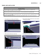
Page 50: ...ted for scratches and dimples prior to installation All claims to be recorded at this time Claims for damage after installation will not receive consideration Black Enamel panels will discolor a little during normal operation This is normal and should not be considered a defect All hand and finger marks MUST be cleaned off with a soft cloth Use an ammonia based cleaner ie glass cleaner to remove a...

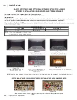
Page 51: ...n using Ceramic Spa Stones DO NOT cover burner ports or pilot light that lead to pilot flame Ensure the crystals or stones do not overlap excessively as this will effect the flame pattern OPTIONAL SPA OR VOLCANICSTONES INSTALLATION AROUND BURNER NOTE Spa or Volcanic Stones are NOT to be placed anywhere on the burner tube or Pilot assembly area NOTE Correct final glass installation of Crystals show...

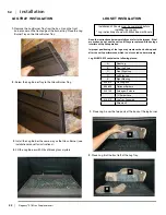
Page 52: ...on back brick panel on the back wall of the firebox 2 Slide in side panel 3 Positon panel so that grout line in the panel lines up with screw in the baffle 4 If required lower screw to secure panel in position 5 Repeat steps 2 4 on other side Line up screw and grout line Final Install BRICK PANEL INSTALLATION ...

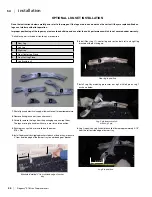
Page 53: ... of the Log Tray Read the instructions below carefully and refer to the images If the logs are broken do not use the unit until they are replaced Broken logs can interfere with pilot operation Improper positioning of the logs may create carbon build up and can alter the unit s performance which is not covered under warranty Log Kit 619 935 contains the following pieces 1 Place Log A over the two p...

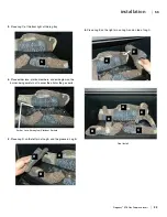
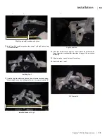
Page 54: ...og tray 4 Place ember lava platinum embers and embaglow on the burner being careful not to cover the pilot or the gas ports 5 Place Log D on the left pin of Log A and the groove in Log B A B C D 6 Place Log E on the right pin on Log A and on top of Log C A A B D C E E Ember Lava Embaglow Platinum Embers Final Install ...

Page 55: ... Carefully remove the logs from the packaging and unwrap them The logs are fragile handle with care never force into position 4 Ensure glass crystals are installed on the burner E18 5lbs 5 Install log brackets by clipping brackets to back of burner tray measure 4 from outside edge of the burner tray to outside edge of bracket Brackets installed 4 from outside edge of burner tray 6 Install Rear Log...

Page 56: ... position E18 final install Installed position of Log 3 1 3 2 4 11 InstalledLog3shouldtouchburnerpositioninthelocationshownbelow Measurement taken from left edge of burner tray approximately 18 12 Position Log 5 rest on pilot hood as shown below 1 5 2 1 2 3 4 18 2 1 4 10 13 Place lava embers rocks on glass ensure rocks do not block pilot Do not place lava rocks embers too close to logs as this may ...

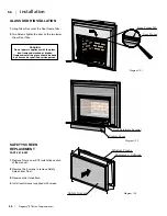
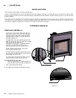
Page 57: ...ontrol cover supplied with screen Control Cover Door Retainers Screws x2 Door Frame Tab Door Frame GLASS DOOR INSTALLATION 1 Hang Glass Door over the Door Frame Tabs 2 Two Screws tighten the door on the two lower Glass Door Tabs Control Cover Door Retainers Screws x2 Door Frame Tab Door Frame Diagram 13 1 Diagram 13 2 Diagram 13 3 WARNING Do not operate appliance with the glass front removed crack...

Page 58: ... may be used DRAFTHOOD CHECK A spillage test must be made before the in stalled unit is left with the customer Follow the procedure below 1 Start all exhaust fans in the home and then close all external doors and windows in the house Remove the Front Trim from the E18 to gain better access to the Drafthood Opening Make sure the Glass Door is on properly 2 Light the unit and set controls to maximum...

Page 59: ...ff and contact a technician OPERATION CONTROLS FIREPLACE CONTROLS The E18 has 3 controls for controlling flame height fan speed and flame on off The fan on the E18 is designed to come on once the fireplace has reached a pre deter mined temperature and to go off once the temperature has dropper following use The speed of the fan can be varied by adjusting the Fan Speed Control dial up or down These...

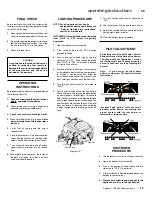
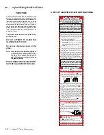
Page 60: ...lly push and release the black button on spark igniter until pilot lights Continue to hold the control knob in for approximately one minute then release the gas control knob The pilot flame should continue to burn If the pilot does not remain lit repeat operation allowing a longer period before releasing gas control knob 6 Verify log placement If the pilot cannot be seen when lighting the unit the...

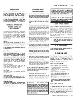
Page 61: ... if any if none follow the National Fuel Gas Code ANSI Z223 1 NFPA 54 or Natural Gas and Propane Installations Codes CSA B149 1 Australia AG601 New Zealand NZS 5261 WARNING If you do not follow these instructions exactly a fire or explosion may result causing property damage personal injury or loss of life Improper installation adjustment alteration serviceormaintenancecancauseinjuryorproperty dam...

Page 62: ...eakage of the glass Do not strike or abuse the glass Do not operate this fireplace without the glass front or with a cracked or broken glass front Wear gloves when removing damaged or broken glass Replacement of the glass panels should be done by a licensed or qualified service per son GLASS REPLACEMENT In the event that you break your glass by impact purchase your replacement from an authorized R...

Page 63: ... instructions in this manual 6 Unplug the TH and TN TP wires on the front of the Valve VALVE REPLACEMENT INSTALLING VALVE 7 Disconnect piezo wire from piezo ignitor 8 Unscrew the 8 screws holding down the Valve Tray 9 Slide the Valve Tray out about half way giving easier access to the gas connection at the valve 1 Place new valve tray and gasket into position 2 Reverse Steps 10 1 3 Check for gas l...

Page 64: ...manual 4 Remove Log Set and Embers or crystals and stones if installed 5 Remove Burner and Panels see instructions in manual 6 Remove Valve Tray see previous page 7 Disconnect Ground Wires and unclip Safety Circuit Wires and remove through Grommet 8 Loosen 4 screws holding in Air Inlet Baffle and remove it 9 Loosen 3 screws holding in the Circulation Fan 10 Disconnect Power Leads on Fan Motor 11 R...

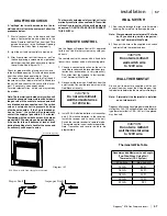
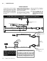
Page 65: ...ce In case of a power failure the fireplace can be turned on but a thermal safety switch will cut out the appliance before it gets to hot The unitl will cycle on and off as required to stay within temperature specifications Caution Ensure that the wires do not touch any hot surfaces and are away from sharp edges When connected with 120 volts the appliance must be electrically grounded in accordanc...

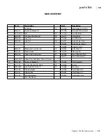
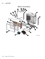
Page 66: ... Brown 616 908 Enamel Panels 7 946 675 Black glass crystals ea 19 904 943 Orifice Mount 8 616 929 Mesh screen 20 910 190 Piezo Ignitor 9 616 040 Glass Door Frame only 21 904 946 Gas Orifice 37 NG 904 977 Gas Orifice 55 LP 616 518 P Glass Door Assembly Glass Frame 10 616 048 Surround Bracket L 22 910 034 Pilot Assembly 11 911 119 Hi Limit Switch N C 230ºF 23 616 526 Burner 12 W241050 Fan Switch N O...

Page 67: ...66 Regency E18 Gas Fireplace Insert 66 parts list 1 2 3 4 5 6 7 8 9 10 11 12 13 14 15 16 17 18 24 19 20 21 22 23 Main Assembly Diagram 20 1 ...

Page 68: ...iption 1 616 070 Adaptor plate gasket 6 E18 Body 2 616 069 Adaptor plate 7 616 068 Surround Panel Rear 3 8 616 067 Surround Front 4 904 960 Ring clamp Installer supplied 9 Magnet and Bracket 5 948 338 Flex Vent Section Installer supplied 10 616 051 Control Cover 616 023 Flue Slider Plate 11 Upper Trim heat shield Diagram 21 1 ...

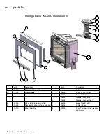
Page 69: ...r plate 7 616 049 Surround Panel Rear 3 8 616 050 Surround Front 9 616 048 Faceplate Hanger Left 10 616 048 Faceplate Hanger Right 4 904 960 Ring clamp Installer supplied 11 904 057 Magnet and Bracket 5 948 338 Flex Vent Section Installer supplied 12 616 051 Control Cover 616 023 Flue Slider Plate 13 616 053 Upper Trim heat shield remove and discard Montigo Econo Plus 28C Installation Kit ...

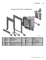
Page 70: ...on Part Description 1 616 070 Adaptor plate gasket 7 E18 Body 2 616 069 Adaptor plate 8 616 068 Surround Panel Rear 3 9 616 067 Surround Panel Right 4 904 960 Ring clamp Installer supplied 10 Magnet and Bracket 5 948 338 Flex Vent Section Installer supplied 11 616 051 Control Cover 6 616 023 Flue Slider Plate 12 Diagram 22 1 ...

Page 71: ...70 Regency E18 Gas Fireplace Insert 70 parts list Montigo 36SR Installation Kit 1 2 3 2 4 5 6 7 8 9 Diagram 23 1 ...

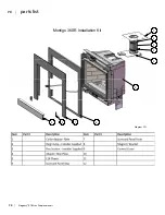
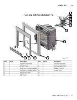
Page 72: ...Regency E18 Gas Fireplace Insert 71 71 parts list Firesong 220N Installation Kit 1 2 3 4 3 5 6 7 8 9 10 Diagram 24 1 ...

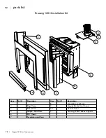
Page 73: ...stallation Kit Item Part Description Item Part Description 8 Faceplate panel Front 3 Ring Clamp 9 Magnet Bracket not shown 4 Flex section 10 Control Cover 5 Adaptor Slide Plate 11 Firesong 120N Firebox supports 6 E18 Chassis 7 Faceplate panel Rear 6 4 5 3 7 8 10 11 11 ...

Page 74: ...Regency E18 Gas Fireplace Insert 73 73 notes ...

Page 75: ...74 Regency E18 Gas Fireplace Insert 74 notes ...

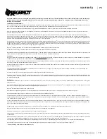
Page 76: ...t parts and issue credit once the replaced component has been returned to Regency and evalu ated for manufacturer defect The authorized selling dealer is responsible for all in field service work carried out on your Regency product Regency will not be liable for results or costs of workmanship from unauthorized service persons or dealers At all times Regency reserves the right to inspect product i...

Page 77: ..._________________________________________________________ Phone ____________________________________________________________ Date Installed _______________________________________________________ Serial No ___________________________________________________________ Register your Regency warranty online www regency fire com Reasons to register your product online today View and modify a list of all...

Reviews: