6
U20/E21 Gas Insert Zero Clearance Kit
INSTALLATION
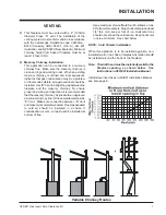
KIT ASSEMBLY
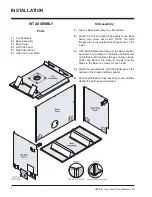
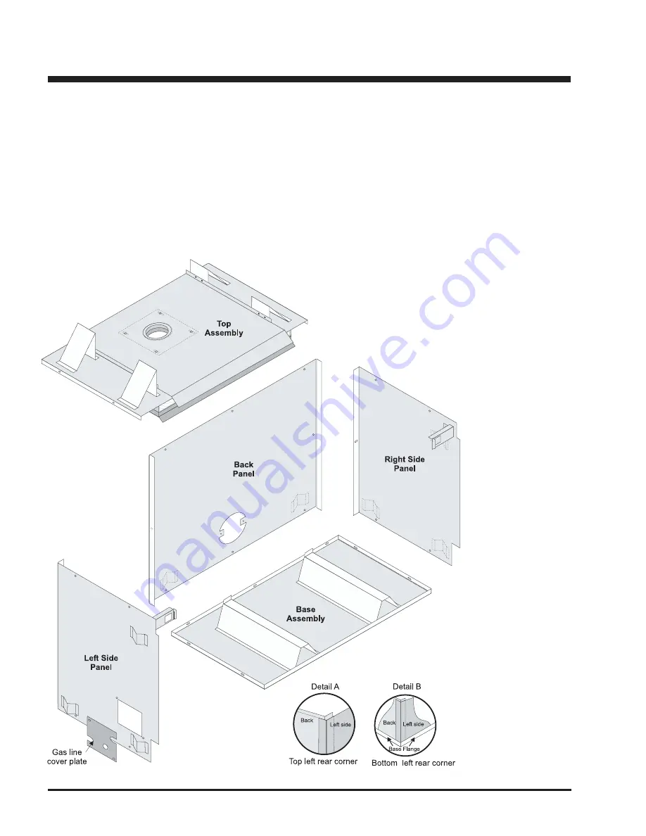
Parts
1) Top Assembly
2) Base Assembly
3) Back Panel
4) Left Side Panel
5) Right Side Panel
6) Gas Line Cover Plate
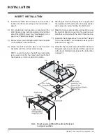
Kit Assembly
1) Lay the Base Assembly on a flat surface.
2) Attach the Left and Right Side panels to the Back
panel (one screw each side). NOTE: the Side
flanges are on the outside, Back flanges are on the
inside.
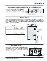
3) Lift the Back/Side Assembly onto the Base, position
as shown in the diagram. The Back and Sides rest
on the Base with the Base flanges on the outside.
Fasten the Back to the Base (3 screws) and the
Sides to the Base (2 screws for each side).
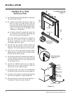
4) Attach the top assembly, with the top flanges on the
outside of the Sides and Back panels.
5)
Do not install the Zero Clearance Top Louver until the
U20/E21 Insert has been installed.
Summary of Contents for Energy E21
Page 12: ...Printed in Canada ...


