background image

12

F37 Regency

®

 Rear Flued Room Sealed Freestanding Gas Heater

System Data - F37

Burner Inlet Orifi ce Sizes:
                 

        NG  LPG

  Burner   

#37 

#52


Max. Input Rating 

31.7 mj

Min. Input Rating 

16 mj


Supply Pressure


 NG 

min. 

1.13kPa

 LPG 

min. 

2.75kPa

Manifold Pressure

 NG 

.89 

kPa 

 LPG 

2.55 

kPa

GAS CONNECTION

The gas connection is a 1/2" NPT Male 
Thread.   Copper can be used or other con-
nections approved by AG 604.

When using copper or fl ex connectors use only 
approved fi ttings. Always provide a union so 
that gas lines can be easily disconnected for 
burner and/or valve servicing. Flare nuts for 
copper lines are  usually considered to meet 
this requirement.

Important: Always check for gas leaks with a 
soap and water solution or gas leak detector. 
Do not use open fl ame for leak testing.

Note:  Prior to any pressure testing of 

the gas supply piping system 
that exceeds test pressures of 
3.45 kPa, this appliance must 
be disconnected from the pip-
ing system.  If test pressures 
equal to or less than 3.45 kPa 
are used then this appliance 
must be isolated from the piping 
system by closing its individual 
manual shut-off valve during the 
testing.

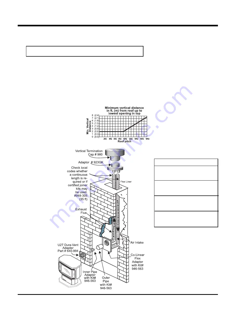
VERTICAL TERMINATION WITH 

CO-LINEAR FLEX SYSTEM

THE APPLIANCE MUST NOT BE CONNECTED TO A CHIMNEY FLUE SERVING 

A SEPARATE SOLID FUEL BURNING APPLIANCE.

This appliance is designed to be attached to two 3" (76mm) co-linear aluminium fl ex running the 
full length of the chimney. See the Flueing Arrangements chart in the "Flue Arrangement" sec-
tion for minimum and maximum  fl ue lengths. See chart  below for minimum distances from roof. 
Periodically check that the fl ue is unrestricted.

Masonry chimneys may take various contours which the fl exible liner will accommodate. However, 

keep the fl exible liner as straight as possible

, avoid unnecessary bending.

The Air Intake pipe must  be attached to the inlet air collar of the termination cap.

Required Parts:

Part # 

Description

946-529 

Co-linear DV Vertical Termination Cap

948-305 

3" Flex - 35 ft.

640-994 F37 

Dura-Vent 

Adapter

946-563 

Co-Axial to Co-Linear Adapter Kit


which contains the following: 

 Co-linear 

Flex 

Adapter 

(270-585) 

 Outer 

Pipe 

(946-257)

 Inner 

Pipe 

Adapter 

(946-219)

Approved Caps

980 Vertical 

Termination 

Cap

923GK 3" 

Co-linear 

Adapter 

 with 

fl 

ashing

INSTALLATION 

Summary of Contents for F37-LPG

Page 1: ...lt an authorized installer service agency or the gas supplier FOR YOUR SAFETY Do not store or use gasoline or other flam mable vapours and liquids in the vicinity of this or any other appliance Installation and service must be performed by an authorized installer service agency or the gas supplier PLEASE KEEP THESE INSTRUCTIONS FOR FUTURE REFERENCE Owners Installation Manual LISTINGS AND CODE APPRO...

Page 2: ...pliances has been designed to provide you with all the warmth and charm of a woodstove at the flick of a switch The models F37 NG and F37 LPG of this series has been approved by AHD for both safety and efficiency As it also bears our own mark it prom ises to provide you with economy comfort and security for many trouble free years to follow Please take a moment now to acquaint yourself with these in...

Page 3: ...Vertical Termination with Co Linear Flex System 12 Gas Connection 12 Conversion from NG to LPG 13 Log Set Installation 14 Aeration Adjustment 14 Door Installation 15 Gas Pipe Pressure Testing 16 Louvre Installation 16 Optional Wall Thermostat 16 Optional Remote Control 17 Wiring 17 Final Check 17 OPERATING INSTRUCTIONS Operating Instructions 18 Lighting Procedure 18 Shutdown Procedure 18 First Fir...

Page 4: ...m Sealed Freestanding Gas Stove We have printed a DATA BADGE copy of the contents here for your review The data plate is located on the inside of the drop down pedestal door NOTE Regency units are constantly being improved Check the label on the unit and if there is a difference the label on the unit is the correct one Australia Only ...

Page 5: ...ilding envelope Never flue to another room or inside a building Make sure that the flue is fitted as per Flueing instructions 5 Inspect the flueing system annually for blockage and any signs of deterioration 6 Flueing terminals shall not be recessed into a wall or siding 7 Any safety glass removed for servicing must be replaced prior to operating the ap pliance 8 To prevent injury do not allow anyone ...

Page 6: ... of the manufacturer LOCATING YOUR REGENCY GAS STOVE When selecting a location for your stove ensure that the clearances listed above are met as well as ensuring that there is adequate accessibility for servicing and proper operation See the Exterior Flue Termination Locations section for Flue Termination requirements ThisapplianceisListedforbedroom installations when used with a Listed Millivolt ...

Page 7: ... non mechanical air inlet or any other opening into a building with the exception of sub floor ventilation see also Note I Appliances up to 150 MJ h input 500 Appliances over 150 MJ h input 1500 k Vertically below an openable window door or non mechanical air inlet or any other opening into a building with the exception of sub floor ventilation see also Note I see table below Clearance k in mm Space...

Page 8: ...tries Ltd Warning Alwaysmaintainrequired clearances air spaces to nearby combustibles to prevent a fire hazard Do not fill air spaces with insulation The minimum clearance requirements between the outer wall of the flue pipe and nearby com bustible surfaces is 30mm Be sure to check the flue termination clearance requirements from decks windows soffits gas regulators air supplyinletsandpublicwalkwaysas...

Page 9: ...reas in the two diagrams below show all allowable com binations of straight vertical and offset to vertical runs with vertical terminations Maximum one 90o elbow All vertical and offset to vertical flue installations require Flue Restrictor to be set to 32mm open If the flue is ENCLOSED in a chase min size 229mm x 229mm maintain a 32mm clearance to combustibles All Vertical Flue Terminals must be Si...

Page 10: ...to adjust the location of the unit 2 Assemble the desired combination of pipe andelbowtotheapplianceadapterwithpipe seamsorienteddown Offsetthepipeseams as double seams in one place will cause the outer pipe to take an oval shape Kit comes complete with 18 457mm of straight flue 6 5 8 168mm dia black outer pipe and 4 102mm dia inner flue 3 With the pipe attached to the stove slide the stove into its...

Page 11: ...ipejoints by using at least two screws Locate the screws at the bottom of the pipe so that the screw heads are hidden on the final installation Apply seal ant Mill Pac to inner pipe and high temp silicone sealant or Mill Pac to outer pipe on every joint Hint Apply sealant to female end c Before connecting the flue pipe to the flue termination slide the black decorative wall thimble cover over the flue...

Page 12: ...isolated from the piping system by closing its individual manual shut off valve during the testing VERTICAL TERMINATION WITH CO LINEAR FLEX SYSTEM THE APPLIANCE MUST NOT BE CONNECTED TO A CHIMNEY FLUE SERVING A SEPARATE SOLID FUEL BURNING APPLIANCE This appliance is designed to be attached to two 3 76mm co linear aluminium flex running the full length of the chimney See the Flueing Arrangements cha...

Page 13: ... by hand from the hi low knob Fig 1 Fig 2 14 Flip the screw Fig 3 Fig 4 Fig 3 15 Using the Allen wrench as shown in Fig 4 rotate the screw clock wise until snug do not overtighten 12 Insert a 5 32 or 4mm Allen wrench into the hexagonal key way of thescrew Fig 2 rotate itcounter clockwiseuntil it is free and extract it 13 Check that the screw is clean and if necessary remove dirt Conversion Kit Con...

Page 14: ...vered under warranty LOG SET INSTALLATION Read the instructions below carefully and refer to the diagrams If logs are broken do not use the unit until they are replaced Broken logs can interfere with the pilot operation The gas log kit contains the following a 02 65 Rear Log b 02 56 Middle Left Log c 02 44 Front Left Log d 02 46 Left Top Log e 02 45 Front Right Log f 02 47 Center Log g 02 48 Middl...
Page 15: ...46 B 02 56 A 02 65 E 02 45 Bracket A 02 65 The bottom right edge of Log G 02 48 must sit snugly against the bracket Side View G 02 48 E 02 45 F 0 2 4 7 3 Close the door The latch plate must be centered around the alignment pin See diagram 2 If the latch plate interferes with the corner of the stove you may want to angle the plate slightly so the door closes easier 7 Place the Left Top Log D 02 46 ...

Page 16: ...ver 3 45 kPa Themanifoldpressureiscontrolledbyaregulator built into the gas control and should be checked at the pressure test point Note To properly check gas pressure both inlet and manifold pressures should be checked using the valve pressure ports on the valve 1 Make sure the valve is in the OFF posi tion 2 Loosen the IN and or OUT pressure tap s turning counterclockwise with a 1 8 wide flat sc...

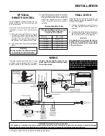
Page 17: ...ol kit comes with a hand held transmitter a receiver and a wall mounting plate 3 Install 3AAAalkaline batteries in transmitter and 4 AA alkaline batteries in the receiver Install the receiver and its cover in the wall Switch the remote receiver to remote mode The remote control is now ready for operation 1 Choose a convenient location on the wall to install the receiver and the receptacle box prot...

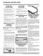
Page 18: ...red as defects in your appliance Blower Regency gasappliancesusehightechblowers to push heated air farther into the room It is not unusual for the fan to make a whirring sound when ON This sound will increase or decrease in volume depending on the speed setting of your fan speed control Burner Tray The burner tray is positioned directly under the burner tube s and logs and is made of a differ ent ...

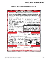
Page 19: ... gas supplier If the pilot will not stay lit after several tries turn the gas control knob to OFF and call your service technician or gas supplier 5 Turn gas control knob counterclockwise to ON 6 Use rocker switch to operate main burner 908 649c Gas Inlet OFF WARNING If you do not follow these instructions exactly a fire or explosion may result causing propertydamage personalinjuryorlossoflife Imp...

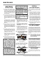
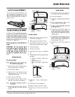
Page 20: ...Continuous condensation can cause corrosion of caps pipe and fittings It may be caused by having exterior portions of the system being exposed to cold weather 3 Inspect joints to verify that no pipe sec tions or fittings have been disturbed and consequently loosened LOG REPLACEMENT The unit should never be used with broken logs Turn off the gas valve and allow the unit to cool before opening door to...

Page 21: ...nter glass 6 Remove glass from extrusions When re moving center glass leave white insulation in place Installing Glass 1 Install both center and side glass onto extrusions as per diagram 2 Place glass assembly into door frame 3 Install retainers by placing 1 drop of glue where previously glued and put in place 4 Install side retainers 5 Install door catch plate 6 Install the 24 nuts loosely do not...

Page 22: ... the stove The fan can only be accessed from the back of the stove IMPORTANT Disconnect power supply before servicing WARNING Electrical Grounding Instructions This appliance is equipped with a three pronged grounding plug for your protection against shock hazard and should be plugged directly into a properly grounded three prong receptacle Do not cut or remove the grounding prong from this plug 3...

Page 23: ...naccessitthroughtherearpedestalcover plate 6 Carefully remove the logs and embers 7 Remove burner See diagram below Note Use a magnetic type screwdriver if possible 8 Remove all 18 screws holding the burner tray assembly in place 9 Carefully lift the burner tray assembly out Be careful not to tear gaskets when lifting out the valve tray these gaskets seal the valve from the exterior of the firebox ...

Page 24: ...23 904 258 Side Panel Door Magnet MAIN ASSEMBLY Part Description Part Description Part Description 24 948 255 Door Latch c w J Hook 25 Flex Pipe 3 ID 26 Clamp for Flex Pipe 27 910 233 Fan Auto On Off Thermodisc 28 Mounting Brckt Thermodisc 29 Air Deflector 30 680 030 Rear Panel 31 630 021F Fan Access Panel 32 730 565 Firebox Baffle Restrictor Assembly 33 640 520 False Top Assembly 35 630 011 Air Pas...

Page 25: ... 60 910 478 Valve S I T NG LPG 904 240 37 Orifice NG 936 170 Orifice Gasket 66 910 038 Pilot Assy S I T 3 Flame NG 67 Pilot Holder 68 W840470 Pilot Assembly Gasket 69 730 935 Log Set 71 730 528 Log Stand 904 390 Pilot Orifice 52 LPG Part Description Part Description PARTS LIST 78 730 550 Burner Assy NG LP 82 630 009 Gasket Burner Tray Air Passage 83 630 008 Gasket Burner Tray Firebox 89 910 096 Pilot...

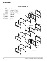
Page 26: ...ete 730 924 Gold Mitred Door Complete 730 926 Black Mitred Door Complete 730 932 Gold Wrap Door Complete 730 928 Gold Panel Door Complete 101 650 920 Door Gasket Kit 105 Ceramic Paper 106 940 323 P Side Glass 107 936 243 Glass Gasket 108 940 322 P Centre Glass 111 Door Frame Fibre Paper 112 750 015 Door Glass Extrusion 208 940 325 P Wrap Glass ...

Page 27: ...pproved service agent is situated more than twenty five 25 kilometres from the installation Australian Heating Distributors are not obliged to arrange warranty repairs and travel and or additional labour charges will apply Exclusions This limited Lifetime Warranty does not extend to or include paint door or glass gasketing or trim It does not cover installation and operational related problems such...

Page 28: ...Printed in Canada Copyright 2006 FPI Fireplace Products International Ltd All rights reserved ...

Reviews: