background image

30

Regency GFI300L Gas Fireplace Inbuilt

MAINTENANCE

ABNORMAL OPERATION

If main burner does not light but pilot  stays  
on,  shut  down  heater  and  contact  your 
dealer. If excessive carbon on logs or glass 
contact your dealer for service.

THE MAJOR CAUSE OF 

OPERATING PROBLEMS WITH GAS 

HEATERS IS IMPROPER 

GAS PRESSURE

Such problems as changes in flame colour 
or configuration, burner outages, intermittent 
operations, changes in heat output, excessive 
burner noise, are nearly always the result of 
changes  in  gas  pressure  or  improper  gas 
pressure at time of installation.

THE MOST IMPORTANT ITEM TO CHECK 
DURING  THE  INSTALLATION  AND  THE 
FIRST  THING  TO  CHECK  WHEN  PROB-
LEMS OCCUR IS GAS PRESSURE.

CHECK DATA PLATE FOR

CORRECT PRESSURE SETTINGS

INCORRECT  INSTALLATION  OR  GAS 
PRESSURE  SETTINGS  ARE  NOT  COV-
ERED  BY  WARRANTY,  A  SERVICE  OR 
CALLOUT  FEE  WILL  BE  CHARGED  IN 
THESE CIRCUMSTANCES

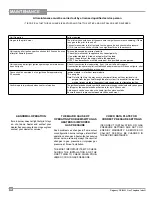
All maintenance must be carried out by a licensed qualified service person

IT IS CRITICAL THAT THIS APPLIANCE IS EARTHED AND THAT THE ACTIVE AND NEUTRAL ARE NOT REVERSED

Unit Operation

Action required

No gas to the pilot burner

The pilot valve should open at the same time the ignition commence sparking. If there 

is no gas to the pilot, turn unit off. 

Connect manometer to inlet test point on the gas valve and check static pressure. 

• If OK, turn unit on and check there is no significant drop in the pressure. 

Unit sparks, pilot ignites, spark continues for 25 seconds, even 

after pilot flame is present

This can be caused by incorrect polarity.
• Check that wall socket to appliance has correct polarity.
•   If an extension lead is fitted, check polarity of the lead.
• Check  the polarity of the supply lead to the appliance.
NOTE:  The above checks must be carried out by a qualified service person.

Unit sparks and pilot light ignites spark stops but main burner 

does not ignite

Check if convection fan is operating, if not, turn unit off and try again. 

If convection fan operates pilot is established and main burner still does not ignite, shut 

down unit and call qualified service person.

Convection fan operates, but no ignition after approximately  

30 seconds

Ignition module is in lockout, reset module.
Turn on again.
Note:  On initial light up, this may occur a number of times until any residual air is 

purged from the gas line through the pilot system. It is essential the required 
waiting time as stated in the manual is observed prior to attempting ignition.

Confirm spark is produced when heater is turned on

The ignition electrode should spark at the same time the gas control solenoid valve opens. 

At this point, the spark electrode will activate for up to 30 seconds.

A blue spark can be seen when the heater ignition process starts.

Ensure the spark is present between electrode and burner.

Summary of Contents for GFI300LLP-R

Page 1: ...cal switch donotuseanyphone in your building Immediately call your gas supplier from a neighbour s phone Follow the gas sup plier s instructions If you cannot reach your gas supplier call the fire depart ment WARNING Improperinstallation adjustment alteration service or maintenance can cause injury or property damage Refer to this manual For assistanceoradditionalinformationconsult an authorised i...

Page 2: ...provide you with all the warmth and charm of a fireplace at the flick of a switch The model GFI300L of this series has been approved by Australian Gas Association for both safety and efficiency As it also bears our own mark it promises to provide you with economy comfort and security for many trouble free years to follow Please take a moment now to acquaint yourself with these instructions and the...

Page 3: ...n 14 Aeration Adjustment 14 Conversion Kit to LP or ULPG 15 Optional Enamel panels 17 Log Set installation 18 Glass door installation 21 Faceplate trim installation 22 Primary Glass guard installation 23 Optional mesh guard installation 23 Wiring 24 Operating Instructions Operating Instructions 25 Lighting Instructions 25 Shutdown Instructions 25 First Fire 25 Remote Control 25 Summary Of Controls...

Page 4: ...of the label that accompanies each Regency GFI300L Gas Inbuilt fireplace We have printed a copy of the contents here for your review DATABADGENOTE Regencyunitsareconstantly being improved Check the label on the unit and if there is a difference the label on the unit is the correct one ...

Page 5: ...Regency GFI300L Gas Fireplace Inbuilt 5 INSTALLATION UNIT DIMENSIONS 236mm 362mm 584mm 288 mm 38mm 908mm 682mm 683 mm 362 mm 100 mm flue ...

Page 6: ...ments burners and circulating airpassagewaysoftheappliancebekeptclean and free from excessive lint from carpeting 4 Seegeneralconstructionandassemblyinstruc tions This appliance may only be installed in a flued non combustiblefireplace Theappliance and flue should be enclosed when installed or passing through a living area where children may come in contact with it 5 Always connect this space heat...

Page 7: ...m cavity requirements are to be maintained to ensure safe and proper operation of the appliance Ensure all construction conforms to local building codes MASONRY INSTALLATION The minimum fireplace dimensions for a masonry installation are shown in the diagrams below 367mm 590mm 688mm 367mm 238mm125mm ...

Page 8: ...LES The minimum fireplace clearances for the Regency gas space heater are shown in the following diagrams From Unit Sides A 464 mm Ceiling B 860 mm Mantle C see Mantel Clearances Min Alcove Width E 1924 mm Max Alcove Depth F 914 mm D E C A B F 4 102mm Allowable mantel leg projection 7 1 8 181mm 10 203mm 13 279mm 1 5 38mm MANTEL LEG 7 178mm MANTEL LEG CLEARANCES Combustible mantel leg clearances as...

Page 9: ...orner Wall Depth 39 9 16 1006mm F Corner Facing Wall Width 56 1422mm I Gas Connection Opening Height 2 51mm J Gas Connection Height 2 5 8 67mm K Gas Connection Inset 3 11 16 99mm L Gas Connection Opening Width 2 1 2 64mm A B C Timber Studs F E I J K L Finished Floor C C Note All framing may be of wood construction OPTIONAL MOCK FIREPLACE ZERO CLEARANCE DIMENSIONS NO MASONRY CHIMNEY ...

Page 10: ...nd bend into the correct shape Bend up at the bend lines until the screw holes in the standoff and the pre punched screw holes on the unit line up 3 Install left and right nailing brackets Remove existing screws from the outside of the unit line up bracket with holes in the unit and secure with 2 removed screws See framing clearance dimensions in the installation manual Mock Fireplace zero clearan...

Page 11: ...ot have to be completely enclosed in a chase You must maintain clearances from the vent to combustible materials See Clearances section Combustible materials can be laid against the side and back standoffs and the stove base 3 Finishing material may be brought to the side and top of the framing do not bring combustible material beyond the framed opening This is both for safety and servicing of the...

Page 12: ...s removed or opened for servicing it must be replaced and closed prior to operating the appliance The glass must be fixed in the door when operating SPECIFICATIONS NG LP ULPG Injector Size 40 2 50mm 53 1 50mm 55 1 30mm Input Rating Max 30 mj Max 27 mj Max 21 mj Min 20mj Min 22 mj Min 17 mj Manifold Pressure 0 9 kPa 2 3 kPa 2 3 kPa Aeration Setting 5 mm 13 mm full open GAS CONNECTION WARNING Only p...

Page 13: ...e operation and must be installed with provisions for adequate combustion and ventilation air avail able to the room in which it is to be operating Air for combustion is drawn in through the front of the unit therefore the front of the unit must be kept DRAFT DIVERTER CONNECTION 1 Attach the flue to the flue collar on the detach able draft diverter The flue collar of the appli ance will fit inside...

Page 14: ...n the safety label 6 When finished reading manometer turn off the unit disconnect the hose and tighten the screw clockwise with a 1 8 flat screwdriver Note Screw should be snug but do not over tighten Note If you have an incorrect flame pattern contactyourRegency dealerforfurther instructions Incorrectflamepatternwillhavesmall probably yellow flames not coming into proper contact with the rear bur...

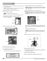
Page 15: ...e logs See log section in this manual 6 Remove the panels See panel section in this manual 7 Remove the log tray by removing 2 screws in locations shown below 8 Lift log tray up and out to remove 9 Remove burner loosen screw on left side remove screw from right side slide to the right and lift up and out to remove and discard Loosen Remove 10 Remove 2 screws in location shown below to remove front...

Page 16: ...t taking care not to obstruct the breather orifice of the pres sure Put back the modulator plastic cap WARNING To ensure the correct operation of the modulator it is necessary that the plastic cap A is returned to its original loca tion 23 Reverse Steps 10 4 3 2 and 1 24 At the end of all setting and adjustment operations check electrical installation and gas leaks 24 Check operation of flame cont...

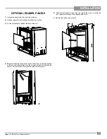
Page 17: ...flat against the back of the unit 4 Before installing the side panels loosen the screws for the tabs enough so that you can slide the tabs on to the screws easily but that the tabs are secure For the location of the side tab screws see diagram 2 5 Slide the side panels into position and tighten the screw to secure the tab repeat to install panel on opposite side of unit 6 Reinstall glass door see ...

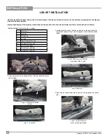
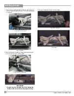
Page 18: ...the bottom of Log 1 with pins behind burner as shown below 2 1 2 Locate pin hole on Log 2 and line up with pin on the right side of the burner The left end of Log 2 will rest against a tab in location shown below 3 Place Log 3 on the centre of the burner rest the log against the centre tabs LOG SET INSTALLATION Logs 1 fits over pins behind burner Logs 2 fits over pin on left side rests against tab...

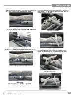
Page 19: ...e proper burner function 5 Place Log 5 across Logs 1 and 2 The left side of the Y in Log 5 fits into the notch in Log 1 The other end of the Log 5 will rest on the burner tray covering the hole as shown below 6 Place Log 6 across Logs 1 and 4 The top part of Log 6 fits into the notch on the left hand side of Log 1 The bottom end of Log 6 should sit so it covers a screw on the burner tray Log 6 fit...

Page 20: ... a tab located on the burner Log 7 fits in notch on Log 6 8 7 8 Log 8 will cover pilot assembly resting on pilot assembly bracket and trim of the burner tray as shown below Log 8 covers Pilot Assembly Log 7 in position 9 Rest Log 9 upright against Log 2 as shown below 9 2 Final Install Log 9 rests on Log 2 IMPORTANT Ensure Log 8 is centered over Pilot Assembly Failure to do so will cause improper ...

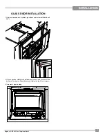
Page 21: ...OR INSTALLATION 1 Lift glass door and slot keyhole in glass door over screw installed in unit body 2 Once in position slide glass door down and secure with 2 screws at the bottom of the door as shown below and tighten the top 2 two screws 3 To remove reverse steps ...

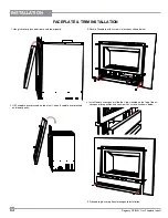
Page 22: ...ure Faceplate with 2 screws in locations shown below 2 Lift Faceplate over brackets on top of unit hook faceplate over brackets and lower gently 4 Install lower access panel slide the 2 tabs located on the top of the ac cess panel into position and secure with 2 screws as shown below 5 Proceed to glass or optional mesh guard installation ...

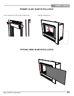
Page 23: ... GFI300L Gas Fireplace Inbuilt 23 INSTALLATION PRIMARY GLASS GUARD INSTALLATION OPTIONAL MESH GUARD INSTALLATION 1 Insert silicone grips into all four 4 glass retaining brackets 2 Slide glass through brackets ...

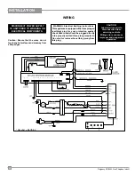
Page 24: ...hing Instructions Thisapplianceisequippedwithathreepronged earthing plug for your protection against shock hazard and should be plugged directly intoaproperlyearthedthree prongreceptacle Do not cut or remove the earthing prong from this plug Caution Ensure that the wires do not touchanyhotsurfacesandareawayfrom sharp edges DISCONNECT POWER SUPPLY TO UNIT PRIOR TO WORKING ON ELECTRICAL COMPONENTS G...

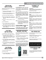
Page 25: ...coldandtheappliance is lit it may cause condensation and fog the glass This condensation is normal and will disappear in a few minutes as the glass heats up DO NOT ATTEMPT TO CLEAN THE GLASS WHILE IT IS STILL HOT DO NOT BURN THE APPLIANCE WITH OUT THE GLASS FRONT IN PLACE FAN OPERATION Set the fan speed on the control panel to adjust to the desired speed Pressing and releasing the plus FAN button ...

Page 26: ...xttothefloorbecause some gas is heavier than air and will settle on the floor WHAT TO DO IF YOU SMELL GAS Do not try to light any appliance Do not touch any electric switch do not use any phone in your building Immediately call your gas supplier from a neighbors phone Follow the gas supplier s instructions If you cannot reach your gas supplier call the fire department B Do not use this appliance i...

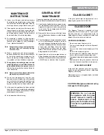
Page 27: ...E Conduct an inspection of the venting system semi annually Recommendedareastoinspectasfollows 1 ChecktheVentingSystemforcorrosioninareas that are exposed to the elements These will appear as rust spots or streaks and in extreme cases holes These components should be replaced immediately 2 Remove the Cap and shine a flashlight down theVent Removeanybirdnests orotherforeign material 3 Checkforevide...

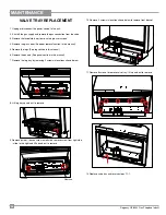
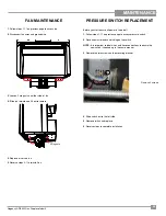
Page 28: ...l 5 Remove the logs See log section in this manual 6 Remove the panels See panel section in this manual 7 Remove the log tray by removing 2 screws in locations shown below 8 Lift log tray up and out to remove 9 Remove burner loosen screw on left side remove screw from right side slide to the right and lift up and out to remove 10 Remove 2 screws in location shown below to remove front bracket Loos...

Page 29: ...sure all power is turned off 1 Follow steps 1 11 on previous page to access pressure switch 2 Disconnect wire leads and tubing on the switch NOTE It is important to label wires and hose connections to ensure the new switch is hooked up in the same manner 3 Remove the two screws on the mounting bracket 4 Slide switch out to the left side 5 Remove switch and replace 6 Reverse steps to complete insta...

Page 30: ...ve and check static pressure If OK turn unit on and check there is no significant drop in the pressure Unit sparks pilot ignites spark continues for 25 seconds even after pilot flame is present This can be caused by incorrect polarity Check that wall socket to appliance has correct polarity If an extension lead is fitted check polarity of the lead Check the polarity of the supply lead to the appli...

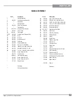
Page 31: ...Assembly Gasket 904 345 Burner Orifice 53 LPG 904 575 Burner Orifice 55 ULPG 911 145 Manual Switch Not shown Not a replacement part Part Description 23 904 553 8 x 1 2 PAN HD PHILLIPS 24 904 926 SCREW 10 32 x 5 8 PAN HEAD 25 904 122 RIVET 1 8 x 1 8 STEEL OPEN END 26 904 578 10 24 x 0 750 PAN HEAD PHILLIPS 28 626 525 Burner Assembly NG 29 626 530 Burner Assembly LP 32 910 155 P Replacement Fan Moto...

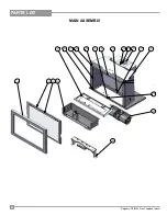
Page 32: ...32 Regency GFI300L Gas Fireplace Inbuilt PARTS LIST MAIN ASSEMBLY 27 9 6 21 24 26 11 4 5 12 16 17 37 1 2 38 28 35 32 33 10 34 ...

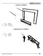
Page 33: ...ireplace Inbuilt 33 PARTS LIST FACEPLATE ASSEMBLY BURNER AND PILOT ASSEMBLY Part Description 45 940 428 P Tempered Glass 46 948 066 Glass Standoff ea Part Description 47 911 146 Pilot Assy NG 911 157 Pilot Assy LP 45 47 46 ...

Page 34: ...34 Regency GFI300L Gas Fireplace Inbuilt NOTES ...

Page 35: ...e Covered under the agreement are the following components Combustion chamber heat exchanger burner tubes logs embers glass thermal breakage and all gold plating against defective manufacture The above will be covered for parts and labour for the first five years and parts only thereafter Electrical components such as fans switches wiring thermodiscs remote control thermopiles thermocouples and ga...

Page 36: ...alled _______________________________________________________ Serial No ___________________________________________________________ Register your Regency warranty online www regency fire com au Reasons to register your product online today View and modify a list of all your registered products Request automatic email notification of new product updates Stay informed about the current promotions ev...

Reviews: